High-voltage cable conveying machine

A wire feeder and cable technology, which is applied in the direction of conveying filamentous materials, thin material handling, transportation and packaging, can solve problems such as unfavorable cable construction, increased wire wear, and large square numbers, and achieves convenient operation, Guaranteed safety and the effect of reducing cable resistance

Pending Publication Date: 2018-04-20
柳州润木电气有限公司
View PDF17 Cites 2 Cited by
  • Summary
  • Abstract
  • Description
  • Claims
  • Application Information

AI Technical Summary

Problems solved by technology

[0002] For the high-voltage large square cable, because of its large square number and heavy weight, it will not rotate spontaneously due to the traction force of the machinery and equipment during the off-line process, and often requires external force to complete it. The common practice is to cooperate with two people, and one person is at the front end. Pull out the wire and cut it with one person, but this method is time-consuming and labor-intensive, and manual operation may increase the wear and tear of the wire, which is not conducive to cable construction

Method used


Image

  • High-voltage cable conveying machine
  • High-voltage cable conveying machine

Examples


Embodiment Construction

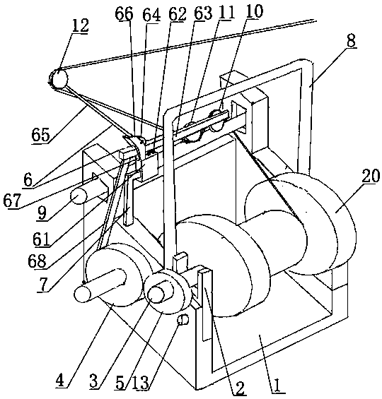
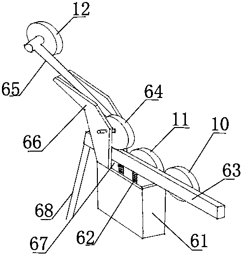
[0026] Such as figure 1 with figure 2 As shown, the cable feeder includes a base 1, a bobbin frame 2, a bobbin 3, a driving gear 4, a driven gear 5, a fixed pulley frame 6, and a fixed pulley block;

[0027] The bobbin frame 2 and the driving gear 4 are respectively installed on the base, and the driven gear 5 is fixedly installed at one end of the bobbin 3, and the bobbin 3 is used to penetrate into the cable winding reel 20 and wind the cable Disc 20 is fixed on the spool 3; said spool 3 is detachably installed on the spool frame 2, when the spool 3 was mounted on the spool frame 2, the driven gear 5 and the driving gear 4 meshed, and the driving gear 4 and the The power mechanism is linked to drive the bobbin 3 to rotate;

[0028] The fixed pulley frame 6 is installed on the base 1 through the fixed rod 7, and is located above the bobbin frame 2. The fixed pulley block is installed on the fixed pulley frame 6, and the cables in the cable winding reel 20 pass through Sen...


PUM


Abstract

The invention aims to provide a cable conveying machine. The cable conveying machine comprises a base, a spool frame, a spool, a driving gear, a driven gear, a fixed pulley frame and a fixed pulley group. The spool frame and the driving gear are mounted on the base. One end of the spool is fixedly provided with the driven gear. The spool is used for penetrating into a cable reel. The cable reel isfixed to the spool. The spool is detachably mounted on the spool frame. When the spool is mounted on the spool frame, the driven gear meshes with the driving gear, and the driving gear is in linkagewith a power mechanism to drive the spool to rotate; and the fixed pulley frame is mounted on the base through a fixing rod and located above the spool frame, the fixed pulley group is mounted on thefixed pulley frame, and a cable in the cable reel passes through the fixed pulley group and then is conveyed out. According to the cable conveying machine, operation is simple, automatic cable conveying is achieved, and cable conveying stability can be adjusted intelligently.

Description

technical field [0001] The invention relates to a high-voltage cable feeding device, in particular to a cable feeding machine. Background technique [0002] For the high-voltage large square cable, because of its large square number and heavy weight, it will not rotate spontaneously due to the traction force of the machinery and equipment during the off-line process, and often requires external force to complete it. The common practice is to cooperate with two people, and one person is at the front end. Pull out the wire and cut it with one person, but this method is time-consuming and labor-intensive, and manual operation may increase the wear and tear of the wire, which is not conducive to cable construction. With the rapid development of modern technology, high-efficiency production has become an inevitable and social consensus. All kinds of equipment are more and more developed in the direction of reducing labor intensity, improving process stability and work efficiency...

Claims


Application Information

Patent Timeline
Patent Type & Authority Applications(China)
IPC IPC(8): B65H49/30B65H51/08
CPCB65H49/30B65H51/08B65H2701/34Y02P70/10
Inventor 蒋冬雷陈海涛杨亚男
Owner 柳州润木电气有限公司
Why Eureka
Try Eureka