Method of constructing steel-concrete composite beam by vertical cable

A technology of steel-concrete composite beams and steel beams, applied in bridges, bridge construction, erection/assembly of bridges, etc., can solve problems such as material waste, achieve broad application prospects, reduce project costs, and improve material utilization efficiency

CN107938520BActive Publication Date: 2019-05-24HENAN PROVINCIAL COMM PLANNING & DESIGN INST CO LTD +2
5 Cites 0 Cited by

Patent Information

Authority / Receiving Office
CN · China
Patent Type
Patents(China)
Current Assignee / Owner
Publication Date
2019-05-24

Smart Images

  • Figure 1
    Figure 1
  • Figure 2
    Figure 2
  • Figure 3
    Figure 3
Patent Text Reader

Abstract

The invention discloses a method adopting vertical stay ropes to construct steel-concrete composite girders. Firstly, steel girder units are prefabricated, multiple temporary suspending pieces are arranged on flanges of steel girders in a spaced way, and meanwhile multiple groups of stay rope devices are correspondingly designed on a bridge girder erection machine; during construction, first holedsteel girder units are erected in place, then suspension clasps at the bottoms of the stay ropes on the bridge girder erection machine are connected with the suspending pieces on the flanges of steelgirders to make the stay ropes in a vertical state, then rope forces of the stay ropes reach set value through stretching and drawing, and then the stay ropes are locked; prefabricated concrete bridge deck slabs are installed; bridge deck slab wet joint concrete is poured, and after the bridge deck slab wet joint concrete reaches the design strength, connection between the stay ropes and the suspending pieces is relieved; then, second holed steel girder units are erected to complete 'simple-bracing variable-continuity' system conversion of two-holed steel girders is completed; by this analogy, construction of a whole connected bridge is completed. The method can improve the material utilization efficiency of traditional support-free steel-concrete composite girder construction, has a series of advantages of quick and convenient construction and the like and has the wide application prospect in large-medium-span composite girder erection.
Need to check novelty before this filing date? Find Prior Art

Description

technical field

[0001] The invention relates to a construction method of a steel-concrete composite beam, in particular to a method for constructing a steel-concrete composite beam by using vertical cables. Background technique

[0002] The steel-concrete composite beam has a series of advantages such as light structure, large spanning capacity, and fast construction speed. It can meet the construction requirements of urban viaducts and long bridges across rivers and seas to the greatest extent, and has been more and more widely used in modern bridge structures.

[0003] Due to the different construction procedures and construction methods of steel-concrete composite beams, their stress states are also different. According to the stress state of the composite beam construction, it can be divided into two types of structures: 1) Live-loaded composite beams, that is, construction without supports. During the construction process, the steel beams and concrete are all borne by t...

Examples

Embodiment Construction

[0033] The construction method of the present invention will be described in more detail below by taking the steel-concrete continuous composite beam with seven holes and one connection as an example, wherein the span range of each steel beam unit is 30-120m, which is more suitable:

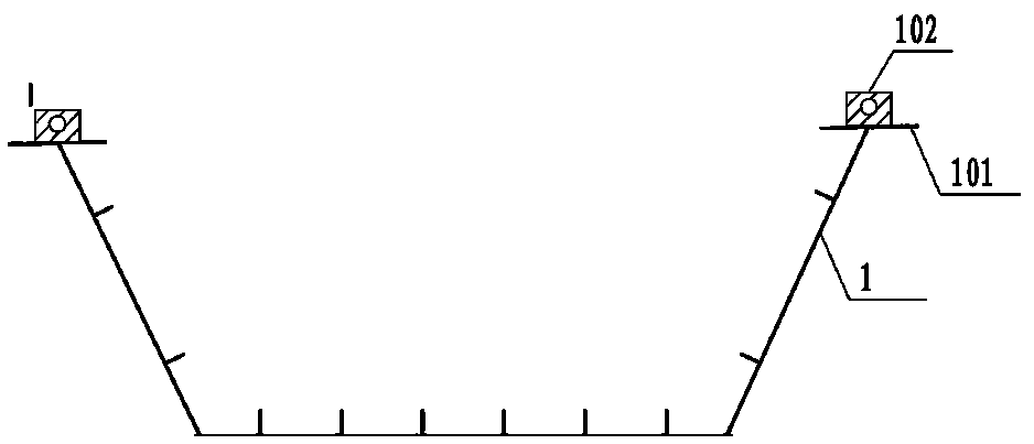
[0034] The first step is to prefabricate the steel beam unit 1 for each hole according to the design requirements, and set a plurality of temporary hanging pieces 102 at intervals on the steel beam flange 101. The structure of the steel beam unit 1 is as follows: figure 1 , figure 2 shown;

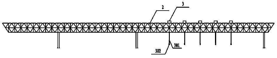
[0035] In the second step, according to the span of the steel girder unit in each hole, multiple groups of cable devices 3 are designed at corresponding intervals on the crossbeam of the bridge erecting machine 2, and the bottom of the cable 301 of each cable device 3 is provided with a temporary hanger piece 102 corresponding to the span. Corresponding to the hanging buckle 302, at the same time, the beam ...