
Auxiliary machine cooling water system achieving high-low position arrangement

A technology of auxiliary cooling water and high and low positions, applied in steam/steam condensers, lighting and heating equipment, etc., can solve problems such as increased risk, difficult procurement, large investment, etc., to improve safety, reduce manufacturing requirements and cost effect

Pending Publication Date: 2018-04-20
NORTHWEST ELECTRIC POWER DESIGN INST OF CHINA POWER ENG CONSULTING GROUP
View PDF7 Cites 0 Cited by
  • Summary
  • Abstract
  • Description
  • Claims
  • Application Information

AI Technical Summary

Problems solved by technology

The outlet pipe of the water tank is connected to the water inlet of the cooling water pump of the auxiliary machine. When the system is in normal operation, the outlet pressure of the cooling water pump of the auxiliary machine will be superimposed on the static pressure of the high-level water tank. The design pressure is about 1.2MPa, which exceeds the design pressure of commonly used equipment. The equipment is a non-standard product, which is difficult to purchase. At the same time, if the manufacturer specializes in producing such high-pressure equipment, the investment will be large, and the risk of system operation will increase. Optimization reduces equipment design pressure

Method used


Image

  • Auxiliary machine cooling water system achieving high-low position arrangement
  • Auxiliary machine cooling water system achieving high-low position arrangement

Examples


Embodiment Construction

[0020] In order to make the objects and advantages of the present invention clearer, the present invention will be further described in detail below in conjunction with examples. It should be understood that the specific embodiments described here are only used to explain the present invention, not to limit the present invention.

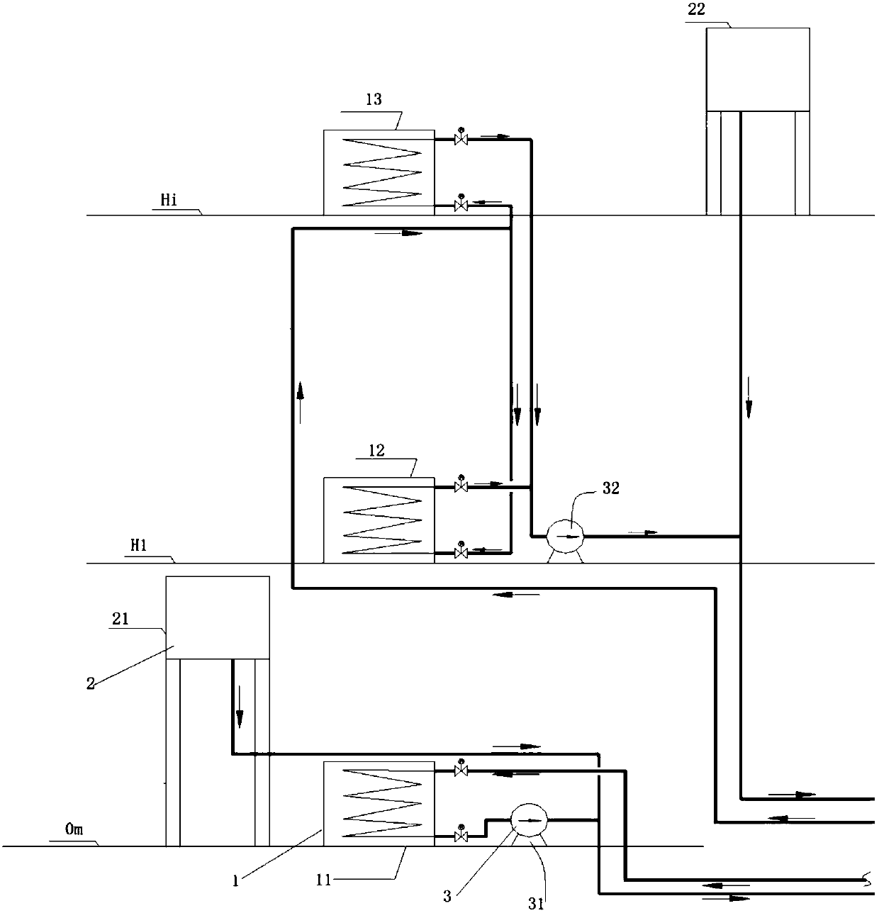
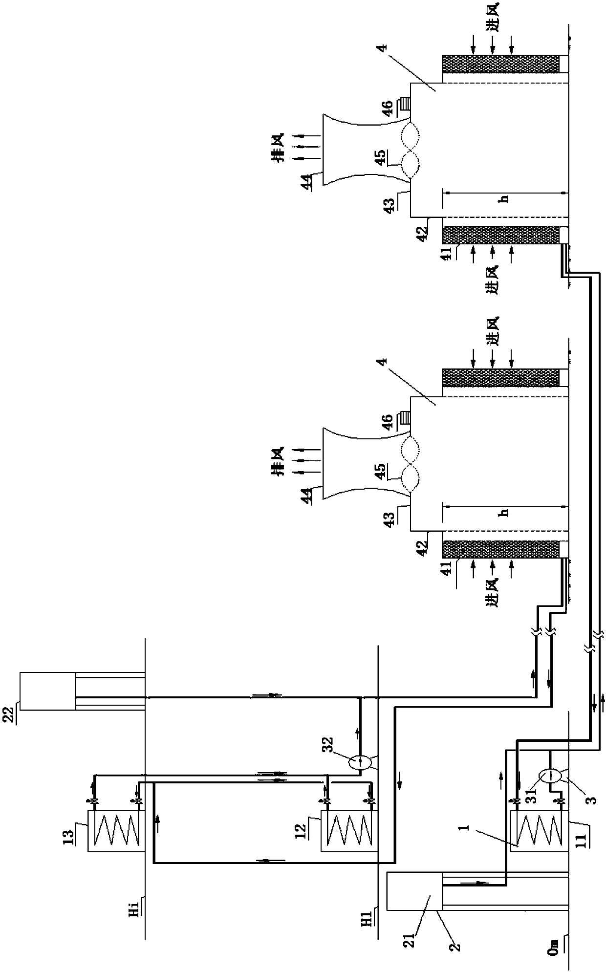
[0021] Such as figure 1 and figure 2 As shown, the present invention divides the auxiliary equipment 1 in the turbine room and the boiler room into high and low pressure areas. For example, above about 43m is the high-level auxiliary equipment, and below 43m is the low-level auxiliary equipment. The high-level auxiliary equipment 1 adopts A set of auxiliary equipment dry cooling system, low-level arrangement Auxiliary equipment equipment 1 adopts a set of auxiliary equipment dry-cooling system, the design pressure of the high-level auxiliary equipment dry-cooling system is about 1.2MPa, and the low-level auxiliary equipment dry cooling system desi...


PUM


Abstract

The invention provides an auxiliary machine cooling water system achieving high-low position arrangement. The auxiliary machine cooling water system comprises multiple auxiliary machine devices sequentially arranged on the ground upwards. The multiple auxiliary machine devices are divided into the high-position arrangement auxiliary machine devices and the low-position arrangement auxiliary machine devices by a division face. An auxiliary machine dry cooling system is adopted by each of the high-position arrangement auxiliary machine devices and the low-position arrangement auxiliary machine devices. The auxiliary machine dry cooling systems comprise high-position water tanks, auxiliary machine cooling water pumps and auxiliary machine dry cooling towers. The multiple corresponding auxiliary machine devices in the high-position arrangement auxiliary machine devices and the low-position arrangement auxiliary machine devices are connected in parallel. In the high-position arrangement auxiliary machine devices or the low-position arrangement auxiliary machine devices, outlets of the auxiliary machine devices are connected with inlets of the auxiliary machine cooling water pumps, outlets of the auxiliary machine cooling water pumps are connected with inlets of the auxiliary machine dry cooling towers, outlets of the high-position water tanks are connected with the outlets of the auxiliary machine cooling water pumps, and outlets of the auxiliary machine dry cooling towers are connected with inlets of the auxiliary machine devices. By means of the system, the manufacturing requirement and cost of the devices are greatly reduced, and meanwhile the safety of device operation is improved.

Description

technical field [0001] The invention belongs to the technical field of thermal power generation air cooling systems, in particular to an auxiliary machine cooling water system arranged in high and low positions. Background technique [0002] When the main engine of a thermal power plant is cooled by a direct air cooling system, when the steam turbine in the main workshop is arranged at a high position, the exhaust steam of the steam turbine is directly connected to the direct air cooling system of the main engine, which saves the steam exhaust device of the steam turbine and shortens the exhaust pipeline, which has the advantages of reducing engineering investment and exhaust steam. The pressure drop of the pipeline improves the operating economy and safety of the direct air cooling unit. This arrangement leads to the layered arrangement of auxiliary equipment in the main workshop, with auxiliary equipment on floors 0m to 65m. At present, the conventional design adopts a se...

Claims


Application Information

Patent Timeline
IPC IPC(8): F28B1/02
CPCF28B1/02
Inventor 赵莉高峰张旸崔光岚
Owner NORTHWEST ELECTRIC POWER DESIGN INST OF CHINA POWER ENG CONSULTING GROUP
Learn More