Power distribution cabinet for community electric room

A power distribution cabinet and power room technology, which is applied in the substation/distribution device casing, electrical components, substation/switch layout details, etc., can solve the problems of noise, inconvenient installation, and inability to move the power distribution cabinet

Inactive Publication Date: 2018-04-20
石爱虎
View PDF0 Cites 0 Cited by
  • Summary
  • Abstract
  • Description
  • Claims
  • Application Information

AI Technical Summary

Problems solved by technology

[0002] The power distribution cabinets in the prior art are all fixed installations, and cannot be moved or rotated after the installation is completed. Therefore, when installing electrical components in the power distribution cabinet, installation will be inconvenient due to different angles, and the distribution cabinet The electrical components installed inside the electric cabinet are different, so the required heat dissipation space is also different. The power distribution cabinet in the prior art cannot be moved and adjusted after installation, so it cannot meet the actual use needs of the power distribution cabinet. , and in some communities, the power distribution room is close to the residents of the community, and the noise generated by the machine during operation makes it difficult to sleep and affects people's rest

Method used


Image

  • Power distribution cabinet for community electric room
  • Power distribution cabinet for community electric room
  • Power distribution cabinet for community electric room

Examples


Embodiment Construction

[0025] Below in conjunction with accompanying drawing and embodiment of description, specific embodiment of the present invention is described in further detail:

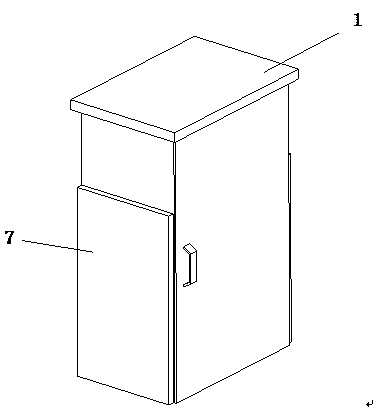
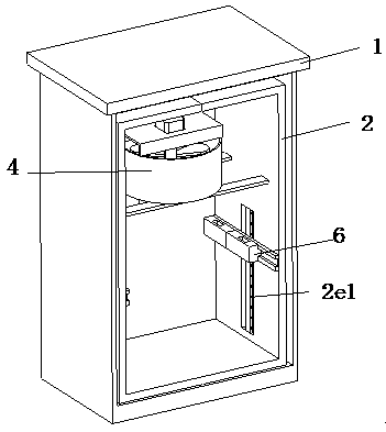
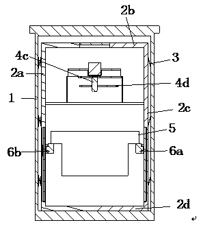
[0026] refer to Figure 1 to Figure 9 A power distribution cabinet for a community electric room is shown, including a cabinet body 1 and an inner frame 2 located in the cabinet body 1, the inner frame 2 is overlapped with the cabinet body 1, and the inner frame 2 and the cabinet body 1 There is a buffer part 3 between them, and the two ends of the buffer part 3 are respectively in conflict with the inner side wall of the cabinet body 1 and the outer side wall of the inner frame 2, and the inner frame 2 is provided with a heat dissipation assembly 4, a mounting plate 5 and an adjustment installation The adjustment assembly 6 of the position of the plate 5 in the inner frame 2, the heat dissipation assembly 4 is located at the upper section of the inner frame 2 and is fixedly connected with the inner frame 2, and the...


PUM


Abstract

The present invention relates to the field of electric equipment, in particular to a power distribution cabinet for a community electric room, comprising a cabinet body and an inner frame located in the cabinet body, the inner frame and the cabinet body are overlapped and matched, and the inner frame and the cabinet body There is a buffer piece, the two ends of the buffer piece are respectively connected with the inner wall of the cabinet body and the outer wall of the inner frame in conflict, and the inner frame is provided with a heat dissipation component, a mounting plate and an adjustment assembly for adjusting the position of the mounting plate in the inner frame , the heat dissipation assembly is located at the upper section of the inner frame and is fixedly connected with the inner frame, the adjustment assembly is located at the lower section of the inner frame and is slidably fitted with the inner frame, the mounting plate is vertically arranged and the two ends of the mounting plate are provided with plugs for the adjustment assembly Connect the mating plug. In the present invention, the cabinet is placed in the electric room of the community, the components are installed on the installation board in sequence, the installation board is plugged and matched with the limit block, and the limit block slides in the slideway to adjust the distance between the installation plate and the inner frame. The distance between the components makes the components have enough heat dissipation space when they are working.

Description

technical field [0001] The invention relates to the field of electric equipment, in particular to a power distribution cabinet for an electric room in a community. Background technique [0002] The power distribution cabinets in the prior art are all fixed installations, and cannot be moved or rotated after the installation is completed. Therefore, when installing electrical components in the power distribution cabinet, installation will be inconvenient due to different angles, and the distribution cabinet The electrical components installed inside the electric cabinet are different, so the required heat dissipation space is also different. The power distribution cabinet in the prior art cannot be moved and adjusted after installation, so it cannot meet the actual use needs of the power distribution cabinet. , and the power distribution room in some communities is close to the residents of the community. The noise generated by the machine during operation makes it difficult ...

Claims


Application Information

Patent Timeline
Patent Type & Authority Applications(China)
IPC IPC(8): H02B1/56H02B1/30H02B1/28
CPCH02B1/565H02B1/28H02B1/30
Inventor 石爱虎
Owner 石爱虎
Why Eureka
Try Eureka