Grid automatic voltage control method and system based on multi-objective optimization

A multi-objective optimization and automatic voltage technology, applied in AC network voltage adjustment, circuit devices, AC network circuits, etc., can solve the multi-objective optimization without considering the number of switching equipment actions, the optimization target only considers a single, does not consider multiple Target optimization and other issues

Active Publication Date: 2018-04-20
STATE GRID HUNAN ELECTRIC POWER +2
View PDF8 Cites 10 Cited by
  • Summary
  • Abstract
  • Description
  • Claims
  • Application Information

AI Technical Summary

Problems solved by technology

For example, the Chinese patent document with the application number 201310111454.1 discloses a reactive power and voltage optimization method and device based on AVC system, which uses the primal dual interior point method, branch boundary method and voltage correction control model method to deal with the coordination of discrete and continuous reactive power sources. Optimizing the control problem does not consider the goal of reducing the number of operations of switching equipment; for example, the Chinese patent document with the application number 201410057500.9 discloses an AVC control method for regional power grids, which considers historical experience and future trends, and blocks and adjusts excessive discrete reactive power. Resource control equipment, which limits the number of adjustments to the expected value of a single discrete reactive power resource, does not involve the coordinated control of discrete and continuous reactive power sources, and does not consider multi-objective optimization; for example, a Chinese patent document with application number 201510079849.7 discloses a control method for an AVC system , the continuous reactive resources are discretized and used as discrete reactive resources to participate in optimization control. The optimization goal only considers a single goal, and does not consider multi-objective optimization including reducing the number of actions of switching equipment

Method used


Image

  • Grid automatic voltage control method and system based on multi-objective optimization
  • Grid automatic voltage control method and system based on multi-objective optimization
  • Grid automatic voltage control method and system based on multi-objective optimization

Examples


Embodiment Construction

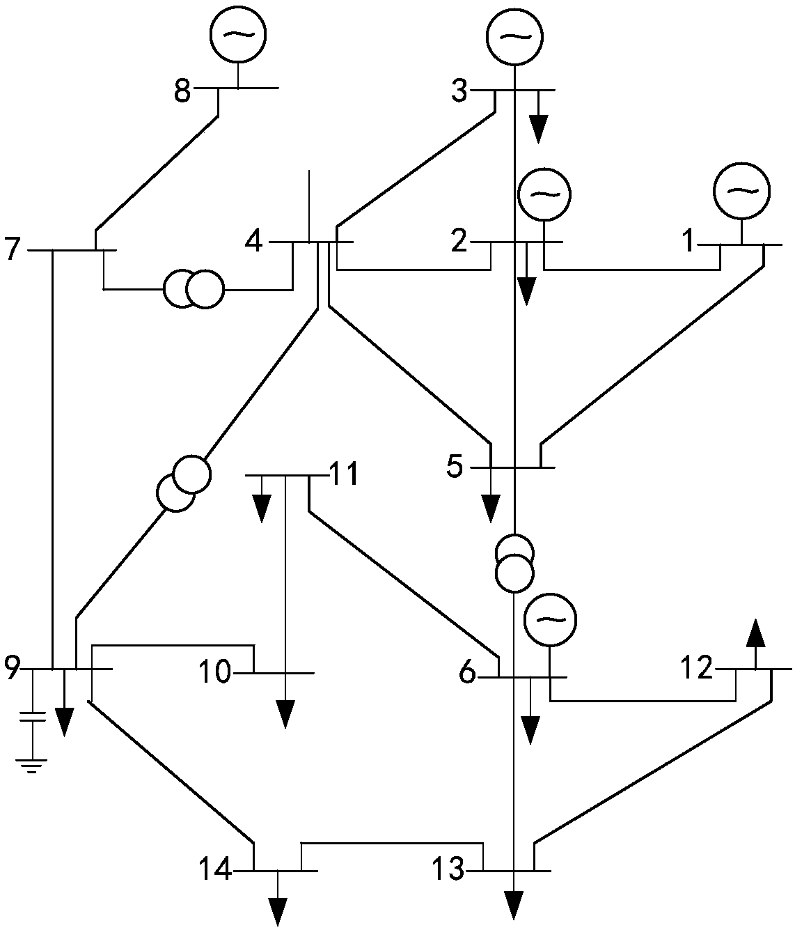
[0041] The following will be figure 1 The typical grid-IEEE-14 node standard system model shown is taken as an example to further describe in detail the grid automatic voltage control method and system based on multi-objective optimization in the present invention.

[0042] see figure 1 , where node 1 is connected to the upper-level power grid and is a balanced node, all nodes are P and Q nodes, and the upper and lower limits (per unit value) of the voltage amplitude of each node are 1.1 and 0.9 respectively, and nodes 2 and 14 are grid-connected For the unit, node No. 5 has dynamic reactive power compensation equipment, nodes No. 3, No. 6, and No. 8 have parallel capacitor banks, and all transformers are no-load tap-changing transformers. The grid model parameters and initial state (0 time) are shown in Table 1. As shown, the resistance, reactance, susceptance, voltage amplitude, active power, and reactive power data are all per unit values, the voltage phase angle is the am...


PUM


Abstract

The invention discloses a grid automatic voltage control method and system based on multi-objective optimization. The method comprises a step of discretizing continuous reactive power resource expected values and participating in gird automatic voltage control with discrete reactive power resources, a step of converting a gird automatic voltage optimization control problem into a multi-objective discrete variable optimization problem with boundary conditions and obtaining an optimal solution according to an artificial intelligence algorithm, a step of solidifying each discrete reactive power resource expected value in the optimal solution, at the same time, carrying out secondary voltage control solution for pilot bus voltage in each region in the optimal solution to obtain an expected value of each continuous reactive power resource. According to the method and the system, multiple optimization objectives such as the reduction of the number of times of action of switching devices andthe reduction of network loss are comprehensively considered, the unified and coordinated optimization of discrete and continuous reactive power resources are effectively realized only through one time of global optimization, the optimization efficiency is extremely high, and the method is established based on a traditional AVC system and is easy to implement.

Description

technical field [0001] The present invention relates to the grid automatic voltage control (AVC) technology of the power system, in particular to a grid automatic voltage control method and system based on multi-objective optimization, which is used for coordinating discrete and continuous reactive resources and reducing the number of actions of grid switching equipment , reduce network loss and other optimization control objectives. Background technique [0002] The Automatic Voltage Control (AVC) system is the main system of voltage and reactive power control in modern power grids. Through the automatic regulation of reactive power resources in the power grid, it can improve the voltage quality of the power grid, reduce network losses, and ensure safe, economical and high-quality operation of the power grid. The reactive power and voltage resources of the modern power grid include various grid-connected units on the power supply side, dynamic reactive power compensation eq...

Claims


Application Information

Patent Timeline
Patent Type & Authority Applications(China)
IPC IPC(8): H02J3/16
CPCH02J3/16H02J2203/20Y02E40/30
Inventor 吴晋波徐昭麟熊尚峰刘海峰朱维钧何晓李敏童争光李理郭思源洪权蔡昱华潘伟徐先勇
Owner STATE GRID HUNAN ELECTRIC POWER
Why Eureka
Try Eureka