Automatic movable device for patient nursing

A technology for automatic movement and patient care, applied in the field of patient care, can solve problems such as unfavorable leg movement and recovery of patients, inability to help patients automatically go up and down stairs, etc., and achieve the effect of simple operation for patients and simple operation of devices

Active Publication Date: 2018-04-24
山东千舒达医疗科技有限公司
View PDF11 Cites 2 Cited by
  • Summary
  • Abstract
  • Description
  • Claims
  • Application Information

AI Technical Summary

Problems solved by technology

However, this device cannot help the patient to go up and down the stairs auto

Method used


Image

  • Automatic movable device for patient nursing
  • Automatic movable device for patient nursing
  • Automatic movable device for patient nursing

Examples


specific Embodiment approach 1

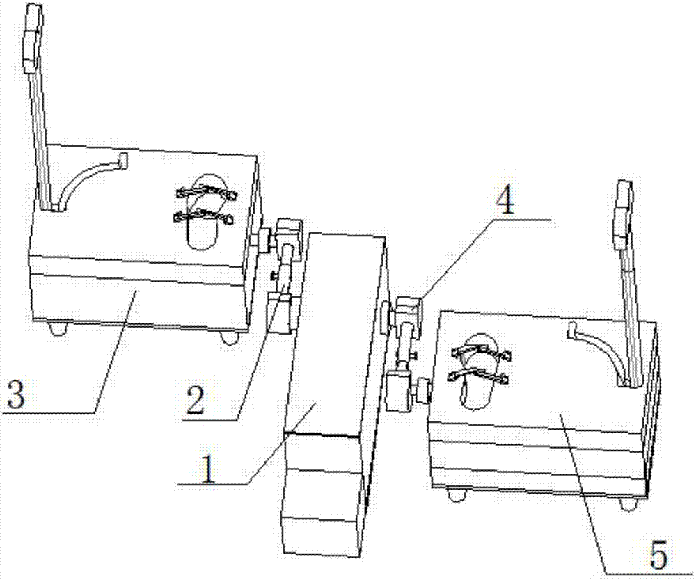
[0028] Such as figure 1 , figure 2 , image 3 , Figure 4 , Figure 5 , Figure 6 , Figure 7 , Figure 8 , Figure 9 and Figure 10 As shown, an automatic moving device for nursing patients includes a main transmission structure 1, a left foot connection structure 2, a left foot movement structure 3, a right foot connection structure 4 and a right foot movement structure 5, the main transmission structure 1 The left and right ends of the left foot connection structure 2 and the right foot connection structure 4 are respectively fixedly connected, the left foot movement structure 3 is fixedly connected to the left end of the left foot connection structure 2, and the right foot connection structure 4 is fixedly connected to the right end of the right foot movement structure 5 .

specific Embodiment approach 2

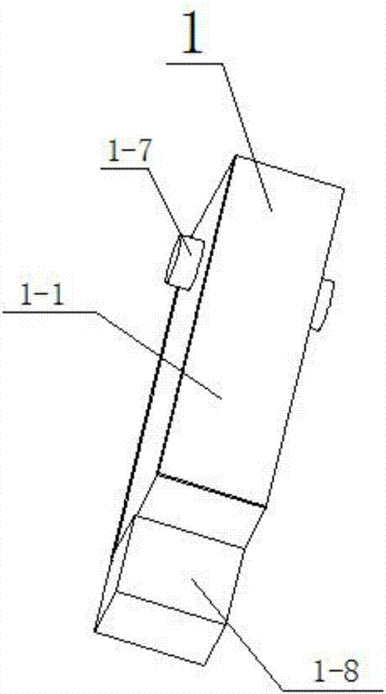
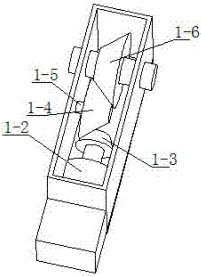
[0029] Such as figure 1 , figure 2 , image 3 , Figure 4 , Figure 5 , Figure 6 , Figure 7 , Figure 8 , Figure 9 and Figure 10As shown, this embodiment will further describe Embodiment 1. The main transmission structure 1 includes an intermediate housing 1-1, a motor 1-2, a main transmission bevel gear 1-3, a transmission bevel gear 1-4, and a transmission shaft 1 -5. From the transmission bevel gear 1-6, the main transmission shaft 1-7 and the rechargeable battery 1-8, the middle shell 1-1 is provided with round holes penetrating left and right, and the rear end of the middle shell 1-1 is provided with a wiring hole, The motor 1-2 is fixedly connected in the middle shell 1-1, the main transmission bevel gear 1-3 is fixedly connected to the output shaft of the motor 1-2, the main transmission bevel gear 1-3 meshes with the transmission bevel gear 1-4, The transmission bevel gear 1-4 is rotatably connected to the transmission shaft 1-5, and the transmission shaf...

specific Embodiment approach 3

[0030] Such as figure 1 , figure 2 , image 3 , Figure 4 , Figure 5 , Figure 6 , Figure 7 , Figure 8 , Figure 9 and Figure 10 As shown, this embodiment will further illustrate the second embodiment. The left foot connection structure 2 includes a universal joint 2-1, a hinge shaft 2-2, a hinge block 2-3, a connection shaft 2-4, The connection sleeve 2-5 and the fixed block 2-6, the connection shaft 2-4 and the connection sleeve 2-5 are all provided with a plurality of threaded holes, and the right end of the universal joint 2-1 is fixedly connected to the hinge shaft 2-2, The right end of the hinged shaft 2-2 turns to connect the hinged block 2-3, the rear end of the hinged block 2-3 is fixedly connected with the connecting shaft 2-4, the connecting sleeve 2-5 is provided with a fixing bolt, and the connecting shaft 2-4 passes through the bolt Connected in the connecting sleeve 2-5, the rear end of the connecting sleeve 2-5 is fixedly connected on the fixed bl...


PUM


Abstract

The invention relates to the field of patient nursing, in particular to an automatic movable device for patient nursing. The automatic movable device for patient nursing comprises a main driving structure, a left foot connecting structure, a left foot moving structure, a right foot connecting structure and a right foot moving structure. The left and right ends of the main driving structure are fixedly connected with the left foot connecting structure and the right foot connecting structure respectively, the left foot moving structure is hinged to the left foot connecting structure, and the right foot connecting structure is hinged to the right foot moving structure. The automatic movable device has the advantages that a patientwho can stand up and cannot walk can be driven by the slow-operation device to walk and move as a normal person, meanwhile, the device is easy to operate, the patient can climb a staircase and steer within a small range, the patient can conveniently stand up andwalk, the patient can move automatically, and the legs of the patient can move and recover conveniently.

Description

technical field [0001] The invention relates to the field of patient care, in particular to an automatic moving device for patient care. Background technique [0002] Patient care tools are recovery aids that are easy for the patient and caregiver to use. Patent No. CN201420482953.1 discloses a novel wheelchair, in particular to an automatic wheelchair capable of going up and down stairs. The automatic wheelchair includes a chassis, a seat, a crawler mechanism, a front wheel mechanism, a rear wheel mechanism and a controller. The chassis has an overall load-bearing box structure; the crawler mechanism includes crawlers, track wheels and crawler driving devices; the front wheel mechanism includes front wheels, front wheel lifting units and front wheel lifting drive devices; the rear wheel mechanism includes rear wheels, rear wheel lifting units And the rear wheel drive; the controller is used to control the seat, track mechanism, front wheel mechanism and rear wheel mechani...

Claims


Application Information

Patent Timeline
IPC IPC(8): A61H3/00
CPCA61H3/00A61H2003/001A61H2003/007
Inventor 赵明桥
Owner 山东千舒达医疗科技有限公司
Why Eureka
Try Eureka