
Brick grinding wheel machine for construction site

A technology for construction sites and grinding machines, which is applied to the parts of grinding machine tools, machine tools suitable for grinding workpiece planes, grinding machines, etc. It can solve the problems of non-compliance with the specifications of broken bricks, rough fractures, and poor fixation of grinding wheels.

Inactive Publication Date: 2018-04-24
李秋平
View PDF0 Cites 0 Cited by
  • Summary
  • Abstract
  • Description
  • Claims
  • Application Information

AI Technical Summary

Problems solved by technology

[0002] In the construction site, the size of the same type of bricks is uniform, but when laying bricks, it is often because of the shape of the building, if some bricks used in special corners do not change the size of the bricks, It will protrude, which is very unsightly, and will affect the stability of the building structure, so it is necessary to break the bricks used in these places, but the end faces of the broken bricks are rough and uneven, and must be ground before At this time, other devices need to be used for grinding. The grinding wheel of the brick grinding wheel machine currently used is not fixed, and it is inconvenient to operate and low in safety; when the existing grinding equipment is grinding, it needs to work Personnel holds bricks and grinds, and the situation that will cause the staff's hands to be tired takes place; If the fracture is too rough, it needs to be polished for a long time, or the specifications of the broken bricks obtained do not meet the requirements, and it is necessary to break the bricks again or use another whole brick to break the bricks, which will cause a lot of time and material waste

Method used


Image

  • Brick grinding wheel machine for construction site
  • Brick grinding wheel machine for construction site
  • Brick grinding wheel machine for construction site

Examples


Embodiment Construction

[0015] The technical solution of this patent will be further described in detail below in conjunction with specific embodiments.

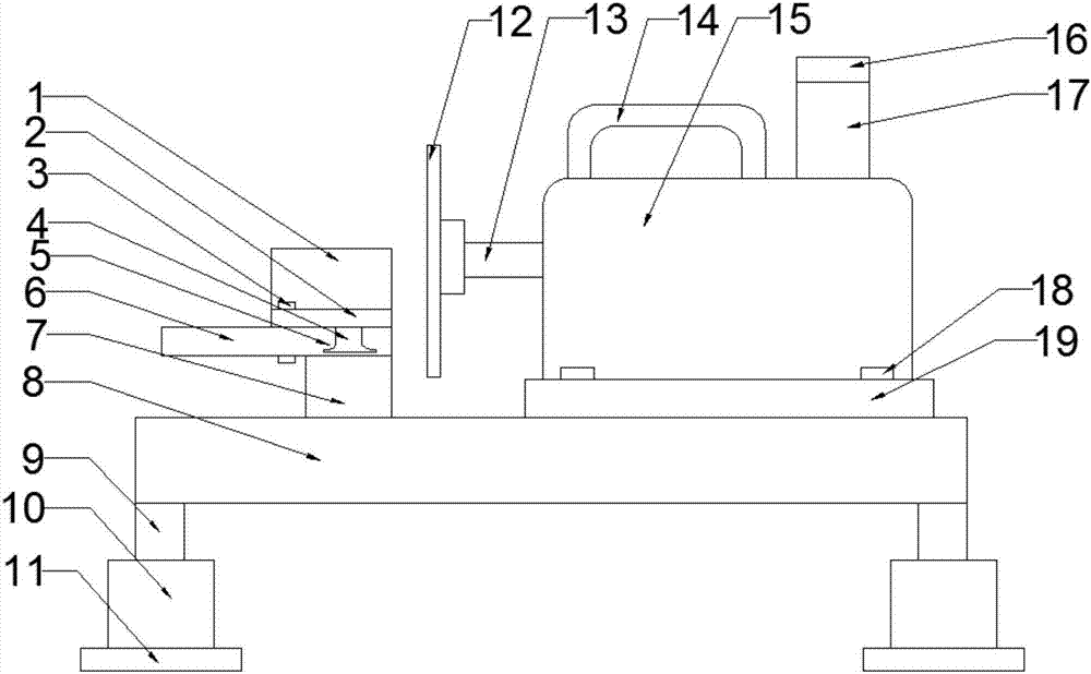
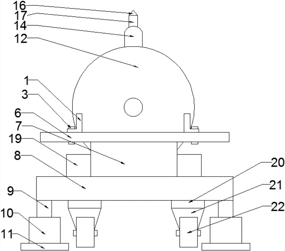
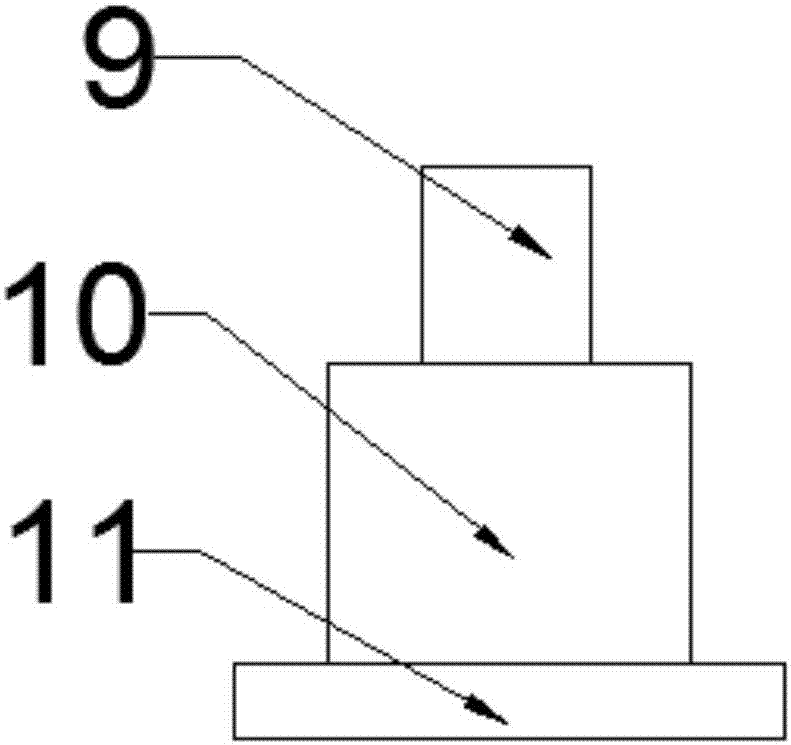
[0016] see Figure 1-3 , the building site uses bricks to grind the grinder, comprising a running gear and a grinding grinder device; the running gear includes a base 8, a telescopic rod 9, a hydraulic cylinder 10, an anchor 11, a shock absorber 20, a wheel bracket 21 and a wheel 22 The four corners of the lower end surface of the base 8 are respectively provided with a hydraulic cylinder 10, and the hydraulic cylinder 10 is connected to the base 8 through a telescoping rod 9; Function; the shock absorber 20 is fixedly arranged on the lower end surface of the base 8 inside the telescopic rod 9, and the shock absorber 20 has the function of reducing damage when the protection device is walking; the wheel bracket 21 is fixedly arranged below the shock absorber 20, and the wheel Wheels 22 are arranged below the support 21, and the wheels 22 have the ...


PUM


Abstract

The invention discloses a brick grinding wheel machine for construction sites, which includes a walking device and a grinding wheel machine device; four corners of the lower end surface of the base are respectively provided with hydraulic cylinders, and the hydraulic cylinders are connected to the base through telescopic rods; The foot is fixed under the hydraulic cylinder; the support brick frame is fixed on the left side of the upper end surface of the base, and the support brick support is connected with the support brick bottom plate; the support brick bottom plate is provided with a chute, and the notch of the chute To become parallel or perpendicular to the grinding wheel, the chute is slidingly matched with the slide rail on the side plate of the supporting brick, and the side plate of the supporting brick is inlaid with steps, and the steps are fixed with the bottom plate of the supporting brick through fastening bolts; the present invention solves the problem of the prior art The problems existing in the operation of breaking bricks can be very convenient to cut off the bricks with broken grooves to obtain broken bricks with relatively neat fractures, thereby reducing the time for grinding the broken bricks again and improving the construction of the entire building. efficiency and avoid material waste.

Description

technical field [0001] The invention relates to the construction field, in particular to a brick grinding wheel machine for construction sites. Background technique [0002] In the construction site, the size of the same type of bricks is uniform, but when laying bricks, it is often because of the shape of the building, if some bricks used in special corners do not change the size of the bricks, It will protrude, which is very unsightly, and will affect the stability of the building structure, so it is necessary to break the bricks used in these places, but the end faces of the broken bricks are rough and uneven, and must be ground before At this time, other devices need to be used for grinding. The grinding wheel of the brick grinding wheel machine currently used is not fixed, and it is inconvenient to operate and low in safety; when the existing grinding equipment is grinding, it needs to work Personnel holds bricks and grinds, and the situation that will cause the staff'...

Claims


Application Information

Patent Timeline
IPC IPC(8): B24B7/16B24B7/22B24B19/02B24B41/06B24B47/12B28D1/22
CPCB24B7/16B24B7/22B24B19/02B24B41/06B24B47/12B28D1/22
Inventor 李秋平
Owner 李秋平
Learn More