Casting floating and rotating mechanism

A technology of rotating mechanism and floating mechanism, which is applied in the direction of grinding workpiece support, grinding drive device, grinding machine tool parts, etc. It can solve the problem of inconvenient grinding of brake discs, and achieve manual or automatic grinding and prevent movement. , the effect of simple structure

Pending Publication Date: 2018-04-24
SUZHOU SUZHU HEAVY IND
View PDF0 Cites 0 Cited by
  • Summary
  • Abstract
  • Description
  • Claims
  • Application Information

AI Technical Summary

Problems solved by technology

[0003] The technical problem to be solved by the present invention is to provide a casting floating rotation mechanism to solve the problem of inconvenient grinding after the brake disc is fixed

Method used


Image

  • Casting floating and rotating mechanism
  • Casting floating and rotating mechanism
  • Casting floating and rotating mechanism

Examples


Embodiment Construction

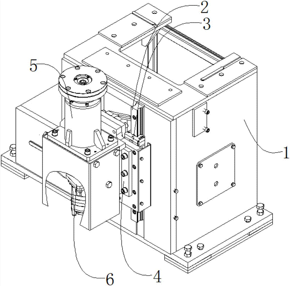
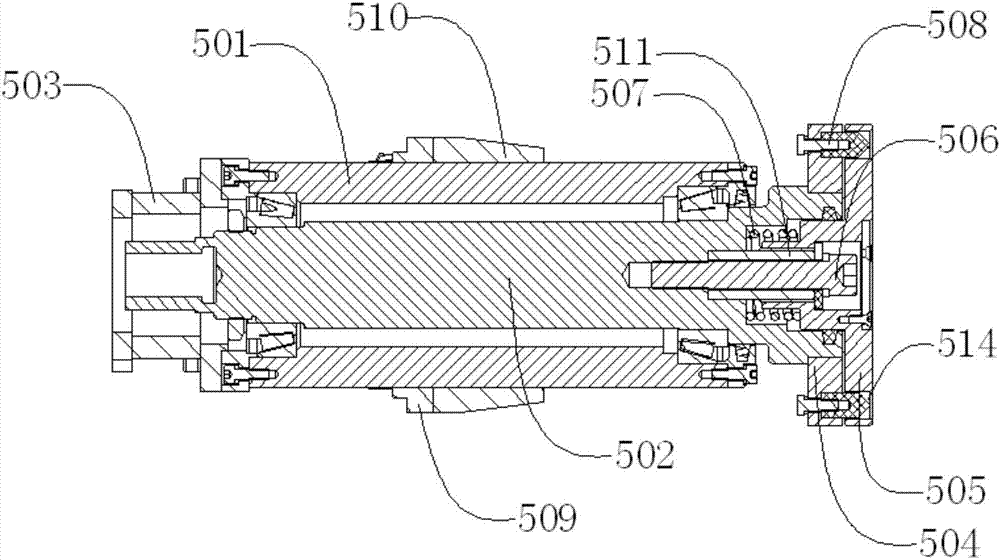
[0019] Such as figure 1 , figure 2 , image 3 As shown, a casting floating rotating mechanism includes a frame 1, a guide rail 2, a slider 3, a sliding plate 4, a floating mechanism 5, and a speed regulating motor 6. The guide rail 2 is located outside the frame 1, and the guide rail 2 is connected with the frame 1 by bolts, the guide rail 2 runs through the slider 3, the slider 3 can move up and down along the guide rail 2, the sliding plate 4 is located outside the slider 3, and the sliding plate 4 It is connected with the slider 3 through bolts, the floating mechanism 5 is located outside the sliding plate 4, the floating mechanism 5 is connected with the sliding plate 4 through bolts, the speed regulating motor 6 is located at the lower end of the floating mechanism 5, and the The speed-regulating motor 6 is connected with the floating mechanism 5 through bolts, and the floating mechanism 5 also includes a shaft sleeve 501, a rotating shaft 502, a motor seat 503, a tran...


PUM


Abstract

The invention discloses a casting floating rotating mechanism, which includes a frame, a guide rail, a slider, a sliding plate, a floating mechanism, and a speed-regulating motor. The height of the mechanism is suitable for castings of different heights. When the casting is placed on the floating mechanism, the speed-regulating motor drives the pressure head to rotate through the rotating shaft, thereby driving the casting to rotate. The device has a simple structure, can drive the casting to rotate automatically, and is convenient for manual or automatic grinding, and through the floating design, it can effectively prevent external forces from interfering with the movement of the rotating shaft, and improve the stability and service life of the movement.

Description

technical field [0001] The invention relates to a mechanical device, in particular to a casting floating rotating mechanism. Background technique [0002] After the casting is poured, there will be a lot of flashes and risers on the surface. These flashes and risers must be removed. For iron castings, they are generally knocked off directly with an oil hammer, while steel castings need to be cut off by gas cutting. Then use the casting grinder to polish the excess flash and pouring riser on the casting to make it smooth and beautiful. At present, electric grinding machines are generally used for grinding. There are fixed large grinding wheel diameter grinding machines and portable small grinding wheel diameter grinding machines. The operation is basically manual operation. During the grinding process of the brake disc, due to the The moving discs are all fixed in advance, so the grinder needs to hold the grinder to move along the circumferential direction of the brake disc ...

Claims


Application Information

Patent Timeline
Patent Type & Authority Applications(China)
IPC IPC(8): B24B41/06B24B47/12
CPCB24B41/06B24B47/12
Inventor 余自马田厚
Owner SUZHOU SUZHU HEAVY IND
Why Eureka
Try Eureka