Adjustable-type casting floating and rotating mechanism

A technology of rotating mechanism and floating mechanism, which is applied in the direction of machine tools, grinding racks, and grinding workpiece supports suitable for grinding the edge of workpieces. It can solve the problems of non-adjustable height, low production efficiency, and high labor intensity. Prevent external forces from interfering with the movement of the shaft, improve production efficiency, improve stability and service life

Pending Publication Date: 2018-04-24
SUZHOU SUZHU HEAVY IND
View PDF5 Cites 1 Cited by
  • Summary
  • Abstract
  • Description
  • Claims
  • Application Information

AI Technical Summary

Problems solved by technology

At present, electric grinding machines are generally used for grinding. There are fixed large grinding wheel diameter grinding machines and portable small grinding wheel diameter grinding machines. The operation is basically manual operation. During the grinding process of the brake disc, due to the The moving disc is fixed in advance, so the grinder needs to hold the grinder to move along the circumferential direction of the brake disc for grinding, which is not only labor-intensive, but also low in production efficiency. At the same time, because the brake disc is fixed, the height cannot be adjusted, resulting in inconvenient

Method used


Image

  • Adjustable-type casting floating and rotating mechanism
  • Adjustable-type casting floating and rotating mechanism
  • Adjustable-type casting floating and rotating mechanism

Examples


Embodiment Construction

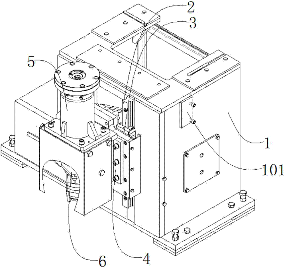
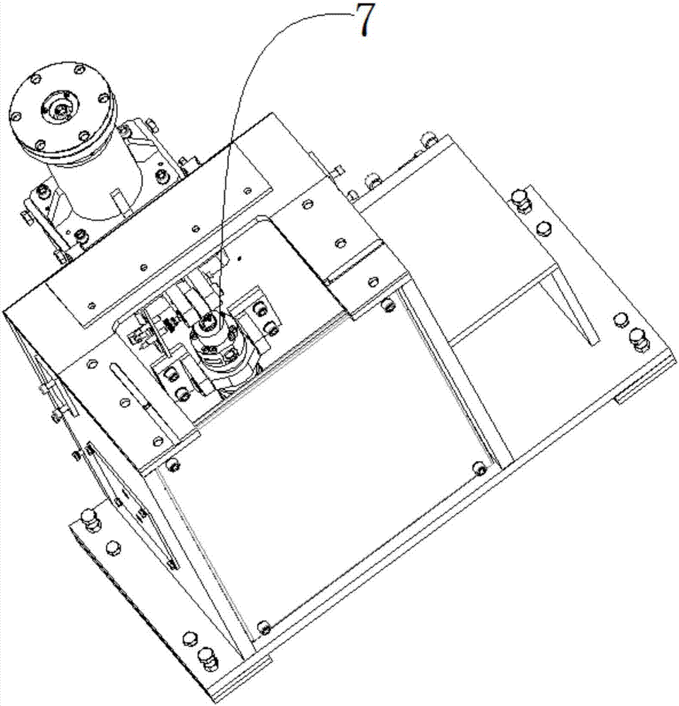
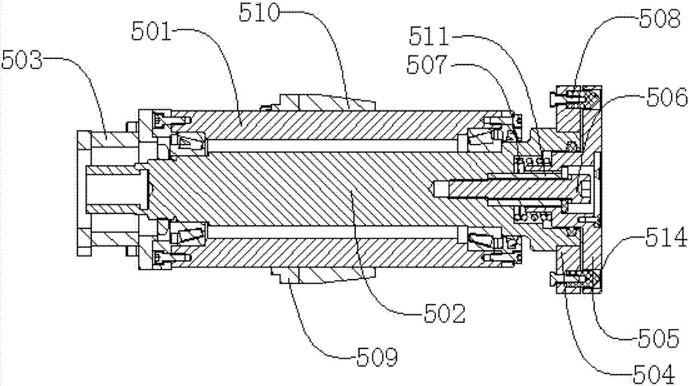
[0022] Such as figure 1 , figure 2 , image 3 , Figure 4 , Figure 5As shown, an adjustable casting floating rotation mechanism includes a frame 1, a guide rail 2, a slider 3, a sliding plate 4, a floating mechanism 5, a speed regulating motor 6, and an adjustment mechanism 7. The guide rail 2 is located on the frame 1 On the outside, the guide rail 2 is connected with the frame 1 by bolts, the guide rail 2 runs through the slider 3, the slider 3 can move up and down along the guide rail 2, and the slide plate 4 is located outside the slider 3, The sliding plate 4 is connected to the slider 3 by bolts, the floating mechanism 5 is located outside the sliding plate 4, the floating mechanism 5 is connected to the sliding plate 4 by bolts, and the speed regulating motor 6 is located on the floating mechanism 5 lower end, the speed-regulating motor 6 is connected with the floating mechanism 5 by bolts, the adjusting mechanism 7 is located inside the frame 1 and on the side of...


PUM


Abstract

The invention discloses an adjustable-type casting floating and rotating mechanism which comprises a rack, a guide rail, a sliding block, a sliding plate, a floating mechanism, an adjustable-speed motor and an adjusting mechanism. When a casting is placed on the floating mechanism, the adjusting mechanism works, and an air cylinder pushes the sliding block fixedly connected with the sliding plateto move along the guide rail, so that the floating mechanism fixedly connected with the sliding plate is pushed to move upwards. When a proximity switch is triggered by a triggering head, the air cylinder stops working, thus the casting is driven to move upwards by a set height, and the adjustable-speed motor drives a pressure head to rotate through a rotary shaft, so that the casting is driven torotate. According to the adjustable-type casting floating and rotating mechanism, the structure is simple, the casting can be driven to automatically rotate and is lifted to the set height, and manual or automatic grinding is facilitated; and through floating-type design, the situation that movement of the rotary shaft is disturbed by external force is effectively prevented, the movement stability is improved, the service life is prolonged, and the production efficiency is effectively improved.

Description

technical field [0001] The invention relates to a mechanical device, in particular to an adjustable casting floating rotation mechanism. Background technique [0002] After the casting is poured, there will be a lot of flashes and risers on the surface. These flashes and risers must be removed. For iron castings, they are generally knocked off directly with an oil hammer, while steel castings need to be cut off by gas cutting. Then use the casting grinder to polish the excess flash and pouring riser on the casting to make it smooth and beautiful. At present, electric grinding machines are generally used for grinding. There are fixed large grinding wheel diameter grinding machines and portable small grinding wheel diameter grinding machines. The operation is basically manual operation. During the grinding process of the brake disc, due to the The moving disc is fixed in advance, so the grinder needs to hold the grinder to move along the circumferential direction of the brake...

Claims


Application Information

Patent Timeline
Patent Type & Authority Applications(China)
IPC IPC(8): B24B9/04B24B41/02B24B41/06B24B55/00
CPCB24B9/04B24B41/02B24B41/06B24B55/00
Inventor 余自马田厚
Owner SUZHOU SUZHU HEAVY IND
Why Eureka
Try Eureka