A connection device for a cable interface of a servo motor

A connection device and servo motor technology, applied in the field of servo motors, can solve problems such as decreased interface connection tightness, interface component damage, and increased time cost, achieving the effects of stable interface, stable structure, and reduced installation time

Active Publication Date: 2022-07-08
广州鲲鹏仪器有限公司
View PDF14 Cites 0 Cited by
  • Summary
  • Abstract
  • Description
  • Claims
  • Application Information

AI Technical Summary

Problems solved by technology

[0003] The servo motor interface and cable connection structure in the prior art is single, and most of them are connected by cables and interfaces or screwed. When the application environment of the servo motor is complicated or the space is small, it is often necessary to connect the cable to the interface. Adjust the cable angle, and the adjustment process of the cable angle will cause sudden changes in the shape of the cable such as bending and folding, so that the internal stress will suddenly increase, and the adjustment process will also cause the cable and the interface to be stressed. When the angle is too large or deformed When it is complicated, the pressure on the interface increases, and long-term use may lead to a decrease in the tightness of the interface connection or damage to the interface components, affecting normal use
In addition, a single connection method of cables and interfaces is difficult to cope with changing working environments. For example, when the motor is in a vibrating working environment, the cable interface will gradually loosen. Once the connection between the cable and the interface drops, it will directly affect the system work. High-precision and high-quality work will lead to greater losses, and the resulting time cost will be greatly increased

Method used


Image

  • A connection device for a cable interface of a servo motor
  • A connection device for a cable interface of a servo motor
  • A connection device for a cable interface of a servo motor

Examples


Embodiment Construction

[0025] The structure of the servo motor cable interface connection device according to the present invention will now be fully described with reference to specific embodiments, so that those skilled in the art can fully understand and implement.

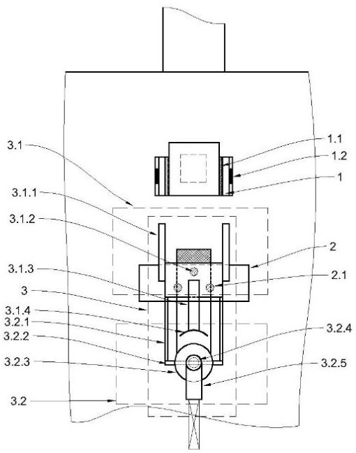
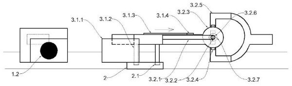
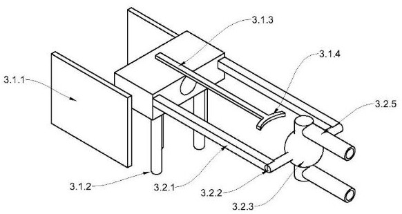
[0026] like Figure 1-Figure 5 Shown: a connecting device for a cable interface of a servo motor. The connecting device includes a cable interface and a cable. The cable interface is located at the front of the side wall of the casing. The orientation of the cable interface is parallel to the casing of the casing. There are two parallel sockets 1 on the left and right sides of the cable interface. The inner plate of the socket 1 is a ceramic plate 1.1, and a permanent magnet suction cup 1.2 is embedded in the side wall of the outer plate. The bracket 2 slides the shell to the cable interface, the bracket 2 is provided with positioning grooves 2.1, the positioning grooves 2.1 are three, and the plane distribution is triangular; The f...


PUM


Abstract

The invention discloses a cable interface for a servo motor and a cable, which belong to the technical field of servo motors; two parallel plug-in interfaces are arranged on the left and right sides of the cable interface; There is a positioning slot; there is an installation sleeve at the cable joint, and the front end of the installation sleeve is the connecting end and the rear end is the direction changing end; The two directional arms are drawn out to form two directional arms, the ends of the directional arms are fixedly connected with a support rod, and the middle of the support rod is interspersed with a direction-changing ball; the outer side wall of the direction-changing ball is provided with two outwardly convex card tables, and the card tables are cylindrical outer sleeves Then the "L"-shaped rotating arm; the direction changing ball, the card table, and the middle of the rotating arm are provided with a cable channel; two sets of wire dividers are fixedly sleeved on the support rod, and the wire divider includes a turntable and a protective cover sleeved on the outside of the turntable , the outlet of each group of protective sleeves corresponds to the outlet of the direction changing ball and a card table respectively. The cable of the present invention is convenient and quick to install and easy to adjust the angle.

Description

technical field [0001] The invention relates to the technical field of servo motors, in particular to a connection device for a cable interface of a servo motor. Background technique [0002] Servo motor is an executive element widely used in automatic control systems and computing devices. It is very accurate in controlling speed and position accuracy, and converts voltage signals into torque and speed to drive the control object. The high-precision control characteristics and working characteristics have high requirements for each component of the servo motor, including the connection of the cable interface between the servo motor and the driver. [0003] The servo motor interface and cable connection structure of the prior art is single, and most of them are plugged into the cable and the interface or fixed by screws. When the application environment of the servo motor is complex or the space is small, it is often necessary to Adjust the cable angle, and the adjustment p...

Claims


Application Information

Patent Timeline
Patent Type & Authority Patents(China)
IPC IPC(8): H02K5/22
CPCH02K5/225
Inventor 李捷
Owner 广州鲲鹏仪器有限公司
Why Eureka
Try Eureka