Fuel nozzle spray cone angle automatic measuring device

A fuel nozzle and spray cone angle technology, which is applied in the field of aero-engines, can solve the problems of low degree of automation, inability to truly reflect the real performance of fuel nozzles, poor precision, etc., to achieve strong applicability, ensure measurement accuracy, and simple and convenient operation Effect

Pending Publication Date: 2019-02-15
中科航空动力(株洲)装备制造研究院有限公司
View PDF0 Cites 3 Cited by
  • Summary
  • Abstract
  • Description
  • Claims
  • Application Information

AI Technical Summary

Problems solved by technology

At present, the measurement of the spray cone angle generally adopts a manual mechanical scale method, which requires manual judgment with the naked eye, and the accuracy is poor and the degree of automation is low.
Of course, there is also an automatic measurement method, by setting the camera to take pictures of the spray cone angle, which only sets up one camera, and sets the fixture for mounting the fuel nozzle to be liftable or rotatable, so that the camera can take pictures of the spray cone angle in multiple directions As we all know, the fuel sprayed by the fuel nozzle is in the form of a spray, which is easily affected by certain factors and changes the original direction. When the fuel nozzle is passively lifted or rotated, the spray cone angle is likely to be forced to change. , the cone angle captured by the camera can no longer truly reflect the real performance of the fuel nozzle

Method used


Image

  • Fuel nozzle spray cone angle automatic measuring device
  • Fuel nozzle spray cone angle automatic measuring device
  • Fuel nozzle spray cone angle automatic measuring device

Examples


Embodiment 1

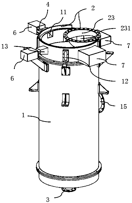
[0033] Provide an automatic measuring device for the spray cone angle of the fuel nozzle, such as figure 1 and figure 2 As shown, it includes a spray chamber 1, the first open end of the spray chamber is provided with a fixture 2 for installing fuel nozzles, and the second open end is an oil return hole 3, and the fixture 2 can make the fuel nozzle under test at the center of the first open end The side wall of the first opening end of the spray chamber 1 is provided with two through holes 11, and one of the through holes is set at a position where the overall situation of the cone angle formed by the fuel nozzle spraying out of the fuel nozzle can be spied on. The CCD camera 4 of angle, on the side wall of the spray chamber, also be evenly distributed with a plurality of transparent plates 12, on the spray chamber 1 outer wall, the light source 5 that can illuminate the spray cone angle place is supported by the supporting structure at each transparent plate setting position...

Embodiment 2

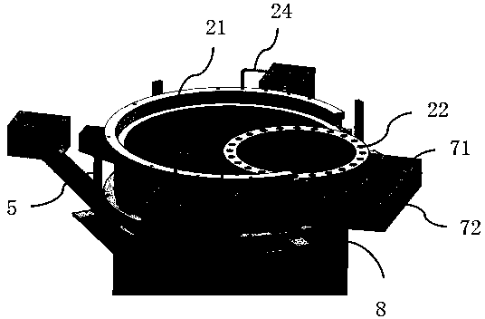
[0048] The difference between this embodiment and embodiment 1 is: the test fixture is a single nozzle fixture, such as Figures 6 to 8 As shown, a single nozzle fixture includes a disc 25 fitted to the first open end and a nozzle installation hole 26 in the center of the disc, and the disc and the nozzle installation hole are connected by a plurality of ribs 27 .

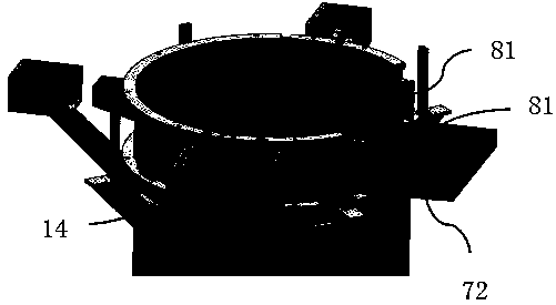
[0049] In order to enhance the versatility of the spray chamber, generally, the spray chamber is uniformly selected as the spray chamber structure described in Embodiment 1. At this time, in order to make the spray chamber also suitable for assembling with a single nozzle fixture, it is necessary to make a single nozzle fixture. Simple structural changes, at this time, a part of the darkroom also needs to be set on the single nozzle fixture, that is, the darkroom is formed by combining the upper half and the lower half, and the upper half is fixed on the outer periphery of the fixture disc. The upper half of the dar...


PUM


Abstract

The invention belongs to the technical field of aviation engines and discloses a fuel nozzle spray cone angle automatic measuring device. The device comprises a spray chamber; the first open end of the spray chamber is provided with a clamp for installing a fuel nozzle; the second open end of the spray chamber is an oil return hole; with the clamp adopted, a fuel nozzle to be tested can be at thecenter of the first open end; at least two through holes are formed in the side wall of the first open end of the spray chamber; at least one of the through holes is disposed properly, so that the comprehensive condition of a taper angle formed by fuel injected from the fuel nozzle can be observed; CCD cameras for shooting the taper angle are arranged at the through holes; and a plurality of lightsources capable of illuminating the spray cone angle are arranged at the side wall of the spray chamber. With the clamp adopted, it can be ensured that the fuel nozzle is at the center of the first open end of the spray chamber; the spray cone angle of the nozzle is measured in multiple directions through the at least two CCD cameras; and the spray of the fuel nozzle is not interfered by externalforces, so that measurement accuracy can be ensured.

Description

technical field [0001] The invention relates to the technical field of aero-engines, in particular to an automatic measuring device for the spray cone angle of a fuel nozzle. Background technique [0002] In the performance test of aero-engine fuel nozzles, it is necessary to measure the nozzle spray cone angle. At present, the measurement of the spray cone angle generally adopts a manual mechanical scale method, which requires manual judgment with the naked eye, and has poor precision and low degree of automation. Of course, there is also an automatic measurement method, by setting the camera to take pictures of the spray cone angle, which only sets up one camera, and sets the fixture for mounting the fuel nozzle to be liftable or rotatable, so that the camera can take pictures of the spray cone angle in multiple directions As we all know, the fuel sprayed by the fuel nozzle is in the form of a spray, which is easily affected by certain factors and changes the original dir...

Claims


Application Information

Patent Timeline
Patent Type & Authority Applications(China)
IPC IPC(8): G01M15/14G01M15/02G01B11/26G01M13/00
CPCG01M15/14G01B11/26G01M13/00G01M15/02
Inventor 廖利华郭斌
Owner 中科航空动力(株洲)装备制造研究院有限公司
Why Eureka
Try Eureka