Supercharge Your Innovation With Domain-Expert AI Agents!

Motor drive device, drive device of compressor using the same, and refrigerator

一种驱动装置、电动机的技术,应用在冷藏库领域,能够解决不能应对稳定性、提高等问题

Active Publication Date: 2020-11-03
PANASONIC INTPROP MANAGEMENT CO LTD
View PDF13 Cites 0 Cited by
  • Summary
  • Abstract
  • Description
  • Claims
  • Application Information

AI Technical Summary

Problems solved by technology

However, it cannot cope with the improvement of stability in the driving state such that the peak voltage of the motor current during sensorless driving overrides the zero-cross signal
Therefore, in the conventional motor drive device shown in Patent Document 3, when the motor current is high in the sensorless drive, there is a problem similar to that of the above-mentioned Non-Patent Document 1.

Method used


Image

  • Motor drive device, drive device of compressor using the same, and refrigerator
  • Motor drive device, drive device of compressor using the same, and refrigerator
  • Motor drive device, drive device of compressor using the same, and refrigerator

Examples


Embodiment approach 1

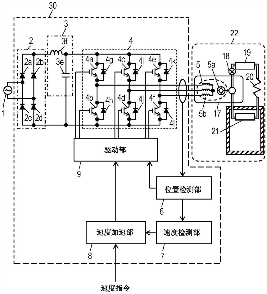
[0077] figure 1 It is a block diagram of the motor drive device according to Embodiment 1 of the present invention.

[0078] figure 1 Among them, the motor driving device 30 is connected to the AC power source 1 to drive the brushless DC motor 5 . The AC power supply 1 is a common industrial frequency power supply, which is a 50Hz or 60Hz power supply with an effective value of 100V in Japan. Hereinafter, the configuration of the motor drive device 30 will be described.

[0079] The rectification circuit 2 receives the AC power supply 1 as an input and rectifies AC power into DC power, and is composed of four bridge-connected rectifier diodes 2a to 2d.

[0080] The smoothing unit 3 is connected to the output side of the rectification circuit 2 and smoothes the output of the rectification circuit 2 . The smoothing unit 3 is composed of a smoothing capacitor 3e and a reactor 3f. The output from smoothing unit 3 is input to inverter 4 .

[0081] In addition, since the rea...

Embodiment approach 2

[0149] The motor drive device 82 according to Embodiment 2 of the present invention will be described. Figure 7 It is a block diagram of a motor drive device according to Embodiment 2 of the present invention. Figure 2, pair with figure 1 The same configurations as those shown in Embodiment 1 are denoted by the same symbols, and description thereof will be omitted.

[0150] In the present embodiment, the configurations of the rectifier circuit 2, the smoothing unit 3, and the inverter 4 constituting the motor drive device 82, and the brushless DC motor 5 constituting the refrigerator 22 are the same as those in the first embodiment.

[0151] In addition, the structure of the position detection part 76 of the motor drive device 82 of this embodiment is the same as that of the position detection part 6 of Embodiment 1. As shown in FIG.

[0152] The speed detection unit 77 calculates the current drive speed of the brushless DC motor 5 and the average speed of one revolution i...

Embodiment approach 3

[0211] Figure 12 A block diagram showing the motor drive device 120 according to Embodiment 3 of the present invention.

[0212] Figure 12 Among them, the power supply 121 is an ordinary commercial frequency power supply, and in the case of Japan, it is a 50Hz or 60Hz AC power supply with an effective value of 100V. The rectifying and smoothing circuit 122 is composed of a rectifying unit 122a and a smoothing unit 122b, receives the AC power supply 121 as an input, and converts the AC voltage into a DC voltage. The rectification and smoothing circuit 122 in this embodiment adopts a voltage doubler rectification structure, but it can also be a full-wave rectification structure, or can be set as a structure switching between full-wave rectification and voltage doubler rectification, or can be a power factor improvement circuit (PFC), etc. .

[0213] In the inverter 123, six switching elements 123a to 123f are connected in a three-phase full-bridge structure, converts the DC i...


PUM


Abstract

The present invention provides a motor driving device, which includes: a brushless DC motor (5), which drives a load that varies during one revolution; and a drive unit (9), which applies a voltage to the brushless DC motor (5) to drive it. The motor drive device further includes a speed acceleration part (8) that determines the voltage applied by the drive part (9) such that the speed within one revolution from the start of the brushless DC motor (5) is relative to the Accelerate so that the rate of change in speed per revolution falls below the specified value.

Description

technical field [0001] The present invention relates to a motor drive device for driving a brushless DC motor, a compressor drive device using the same, and a refrigerator. Background technique [0002] In the prior art, in such a motor drive device, if the motor is driven by PWM control and the motor speed is increased relative to the target speed, the PWM on-time will be reduced, and if the motor speed is reduced relative to the target speed , will increase the on-time. [0003] In addition, in a refrigerator cooled by an existing motor drive device, a four-way valve is installed in the refrigeration cycle. When the compressor is running, the normal refrigeration cycle is used to operate, and when the compressor is stopped, the four-way valve is switched. The valve separates the high-pressure side and the low-pressure side in circulation, and supplies high-pressure refrigerant from the dryer to the compressor, and the pressure difference between the suction and discharge ...

Claims


Application Information

Patent Timeline
Patent Type & Authority Patents(China)
IPC IPC(8): H02P6/20H02M7/5387F25B49/02H02P6/182H02P6/08H02P6/16
CPCH02P6/08H02P6/20H02P6/182F25B49/02F25B2500/26F25B2500/27F25B2600/2513H02P6/16H02P2207/05H02M7/53871
Inventor 竹冈义典田中秀尚
Owner PANASONIC INTPROP MANAGEMENT CO LTD
Features
  • R&D
  • Intellectual Property
  • Life Sciences
  • Materials
  • Tech Scout
  • Unparalleled Data Quality
  • Higher Quality Content
  • 60% Fewer Hallucinations
Learn More