Quantifying device and cooking utensil

A quantitative device and cooking utensil technology, applied in the field of kitchen utensils, can solve problems affecting the quality of rice cooking, affecting weighing accuracy, sensor deformation, etc., to achieve the effect of ensuring good fit, optimizing appearance, and increasing quality

Pending Publication Date: 2018-04-27
FOSHAN SHUNDE MIDEA ELECTRICAL HEATING APPLIANCES MFG CO LTD
View PDF4 Cites 2 Cited by
  • Summary
  • Abstract
  • Description
  • Claims
  • Application Information

AI Technical Summary

Problems solved by technology

[0002] At present, intelligent cooking appliances such as automatic rice cookers mostly use sensors for weighing, but the sensor is easily deformed under pressure, which affects the weighing accuracy, and the rice-water ratio will be out of balance, affecting the quality of rice cooking

Method used


Image

  • Quantifying device and cooking utensil
  • Quantifying device and cooking utensil
  • Quantifying device and cooking utensil

Examples


Embodiment 1

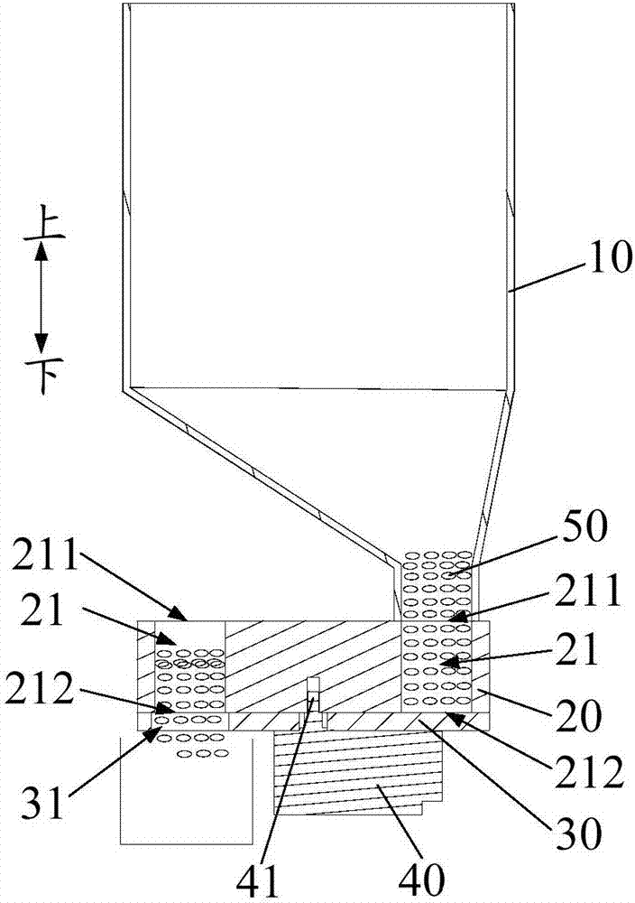
[0052] Quantitative block 20 is cylindrical, and can rotate along the central axis of quantitative block 20, as Figure 5 and Figure 7 Shown; The shield 30 is a circular baffle, such as Figure 6 shown.

[0053] The quantity of quantitative tank 21 is multiple, as Figure 5 and Figure 7 As shown, wherein, when the discharge port 212 of any one of the multiple quantitative tanks 21 is connected to the feed port 31 , the feed port 211 of at least one of the remaining quantitative tanks 21 is connected to the discharge port 11 .

[0054] Preferably, as Figure 5 and Figure 7 As shown, there are two quantitative grooves 21 , and the two quantitative grooves 21 are symmetrically distributed on the quantitative block 20 . Wherein, quantitative groove 21 is strip-shaped quantitative groove 21, and strip-shaped quantitative groove 21 bends and is arc-shaped, as Figure 5 and Figure 7 shown.

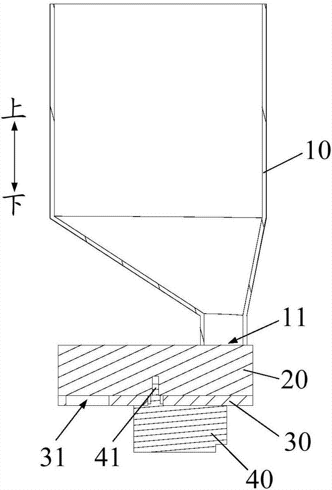
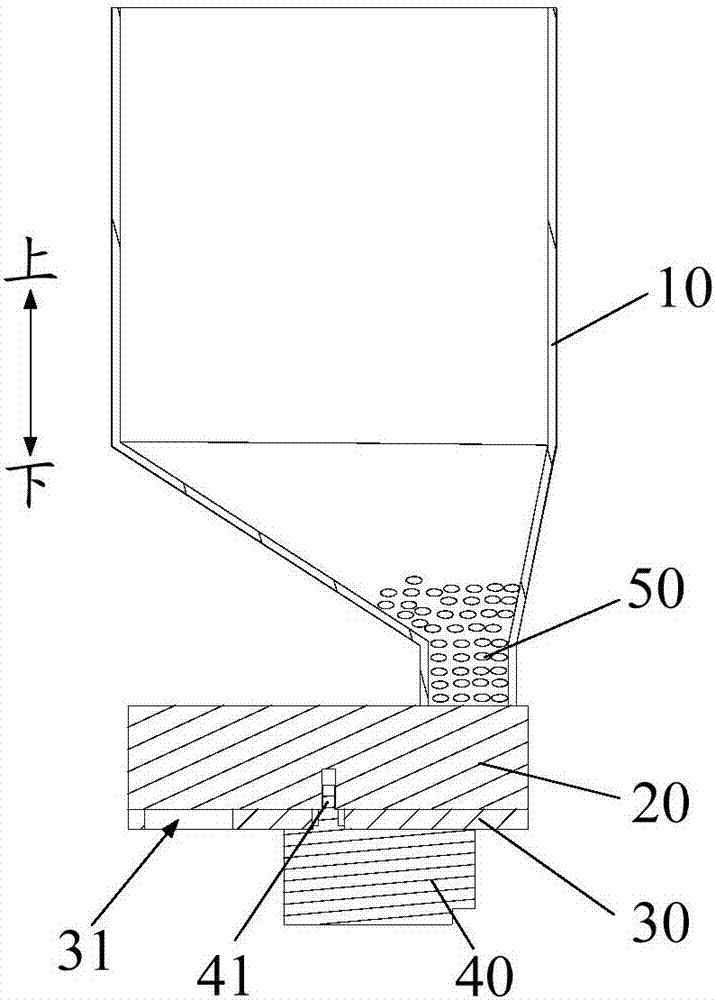
[0055] Further, as Figure 1 to Figure 3 As shown, the quantitative block 20 is...

Embodiment 2

[0066] Embodiment two (not shown in the figure)

[0067] The difference from Embodiment 1 is that there is only one quantitative tank 21 .

[0068] The specific working principle of this embodiment is the same as that of Embodiment 1, and will not be repeated here.

[0069] Since the volume of the quantitative tank 21 is fixed, the purpose of quantitative feeding can also be achieved.

Embodiment 3

[0070] Embodiment three (not shown in the figure)

[0071] The difference from Embodiment 1 is that there are multiple quantitative grooves 21, and the sizes of the multiple quantitative grooves 21 are not exactly the same.

[0072] The specific working principle of this embodiment is the same as that of Embodiment 1, and will not be repeated here.

[0073] Among the multiple quantitative tanks 21, some quantitative tanks 21 with relatively large sizes can be designed, and some quantitative tanks 21 with relatively small sizes can be designed.

[0074] In this way, quantitative grooves 21 of different sizes can be combined to form more quality combinations, thereby satisfying different demands of different users. Since the size of each quantitative tank 21 is fixed, the quality of the material 50 that can be stored and discharged by each quantitative tank 21 is also fixed, so the purpose of the present invention can also be achieved.


PUM


Abstract

The invention provides a quantifying device and a cooking utensil. The quantifying device comprises a storage box, a sheltering part and quantifying blocks, wherein a material discharge hole is formedin the storage box; a material feed hole is formed in the sheltering part; the quantifying blocks are positioned between the storage box and the sheltering part, quantifying grooves are formed in thequantifying blocks, two ends of each quantifying groove are open and form a material feeding end hole and a material discharging end hole, the quantifying blocks can rotate relative to the storage box and the sheltering part, so that the material feeding end hole communicates with or is isolated from the material discharge hole, and the material discharging end hole communicates with or is isolated from the material feed hole; when the material feeding end hole communicates with the material discharge hole, the material discharging end hole is isolated from the material feed hole; when the material discharging end hole communicates with the material feed hole, the material feeding end hole is isolated from the material discharge hole. For the quantifying device provided by the invention,through the match among the storage box, the quantifying blocks and the sheltering part, the volume quantifying during material feeding is realized, so that the mass quantifying of the materials during material feeding is realized, the feeding precision of the quantifying device is effectively guaranteed, and in addition, the structure is simple and compact.

Description

technical field [0001] The invention relates to the field of kitchen utensils, in particular to a dosing device and a cooking utensil comprising the dosing device. Background technique [0002] At present, intelligent cooking appliances such as automatic rice cookers mostly use sensors for weighing, but the sensors are prone to deformation under pressure, affecting the weighing accuracy, and the rice-water ratio will be out of balance, affecting the quality of rice cooking. Contents of the invention [0003] In order to solve at least one of the above technical problems, an object of the present invention is to provide a dosing device. [0004] Another object of the present invention is to provide a cooking appliance comprising the above-mentioned dosing device. [0005] In order to achieve the above object, the embodiment of the first aspect of the present invention provides a quantitative device, including: a storage box, the storage box is provided with a discharge por...

Claims


Application Information

Patent Timeline
Patent Type & Authority Applications(China)
IPC IPC(8): A47J47/01A47J36/00
CPCA47J36/00A47J47/01
Inventor 梅若愚陈炜杰何柏锋潘典国刘小凯周亚
Owner FOSHAN SHUNDE MIDEA ELECTRICAL HEATING APPLIANCES MFG CO LTD
Why Eureka
Try Eureka