Flow collector and centrifugal fan adopting flow collector

A current collector and air surface technology, which is applied in the field of current collectors, can solve the problems of small flow, high noise, and inability to effectively improve fan efficiency, and achieve the effects of reducing oil fume flow, reducing fan noise, and shielding sound transmission

Pending Publication Date: 2018-04-27
NINGBO FOTILE KITCHEN WARE CO LTD
View PDF3 Cites 9 Cited by
  • Summary
  • Abstract
  • Description
  • Claims
  • Application Information

AI Technical Summary

Problems solved by technology

[0004] For these current collectors mentioned above, due to the asymmetry of the flow field in the volute, especially the flow rate near the volute tongue of the current col

Method used


Image

  • Flow collector and centrifugal fan adopting flow collector
  • Flow collector and centrifugal fan adopting flow collector
  • Flow collector and centrifugal fan adopting flow collector

Examples


Embodiment Construction

[0022] The present invention will be further described in detail below in conjunction with the accompanying drawings and embodiments.

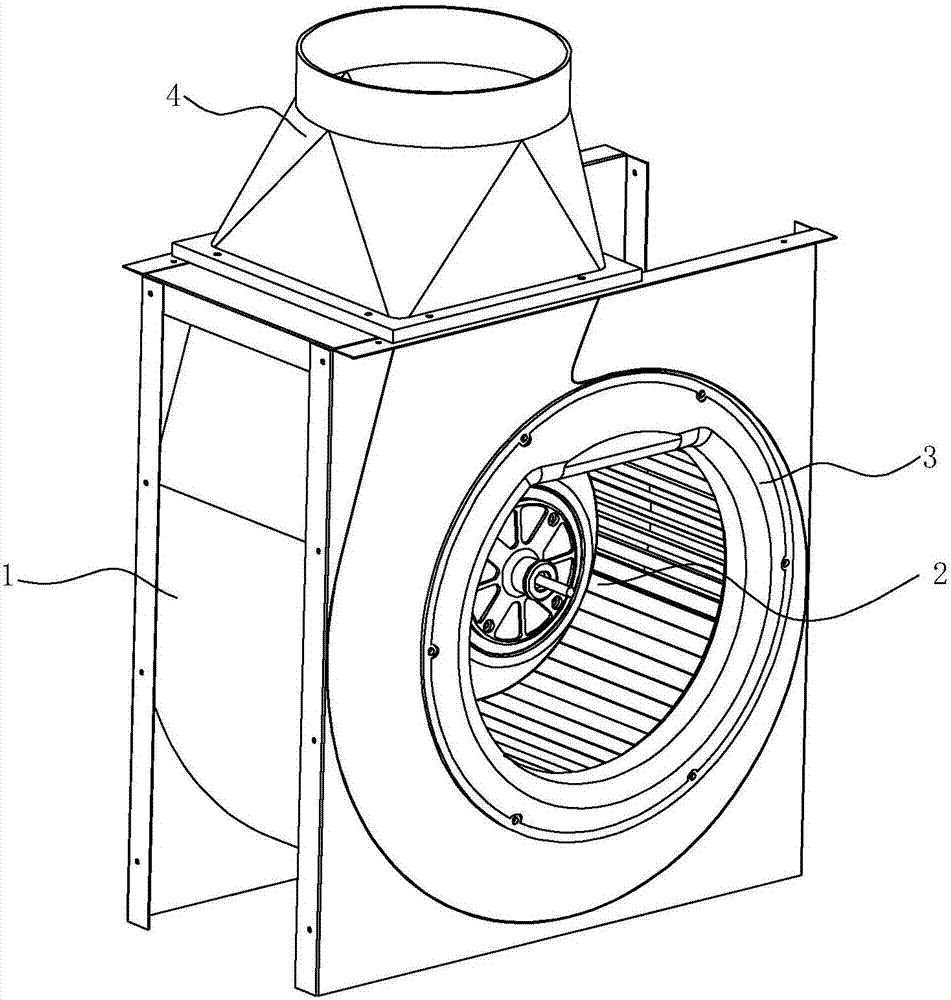
[0023] see Figure 1 to Figure 5 , a current collector for centrifugal fans, which are mainly used for range hoods.

[0024] The centrifugal fan includes a volute 1, an impeller 2 arranged in the volute 1, and a collector 3. The volute 1 has a volute tongue 11 near the air outlet, and the collector 3 is arranged at the air inlet on the front side of the volute 1. And coaxial with impeller 2. When the impeller 2 rotates, the air in the volute 1 is discharged out of the volute 1 through the air outlet cover 4 arranged at the air outlet of the volute 1, and a negative pressure is formed inside the volute 1, and the oil fume passes through under the action of the negative pressure. After the current collector 3 enters the volute 1, it is discharged to the public flue or out of the room under the action of the impeller 2.

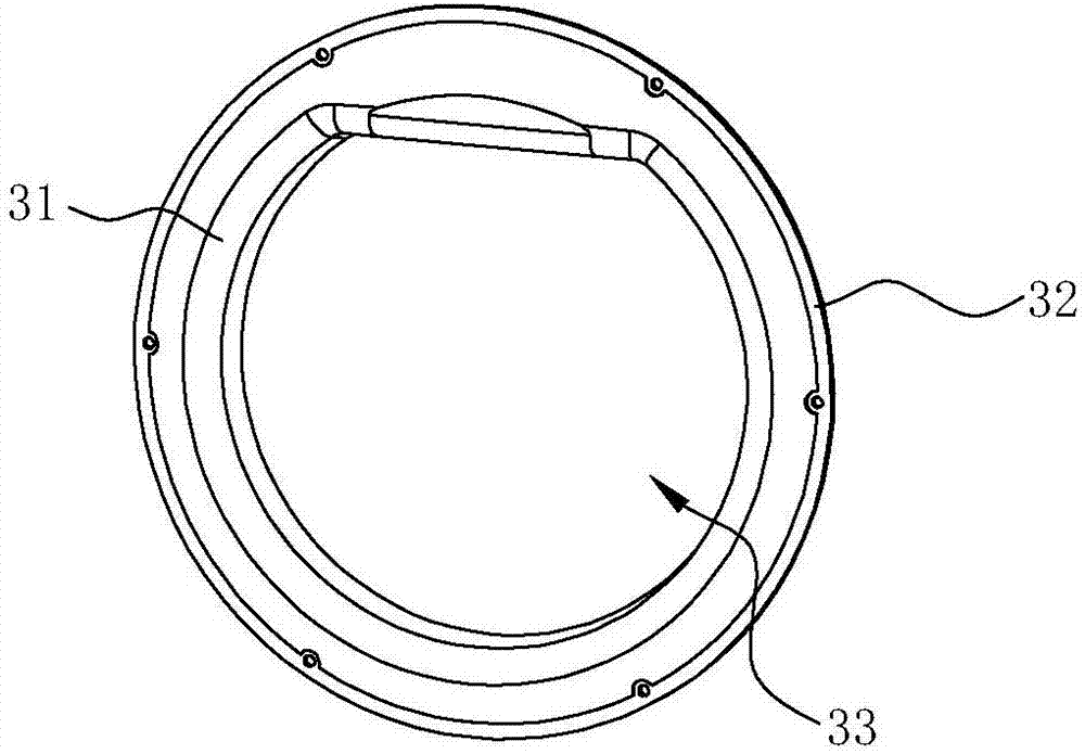
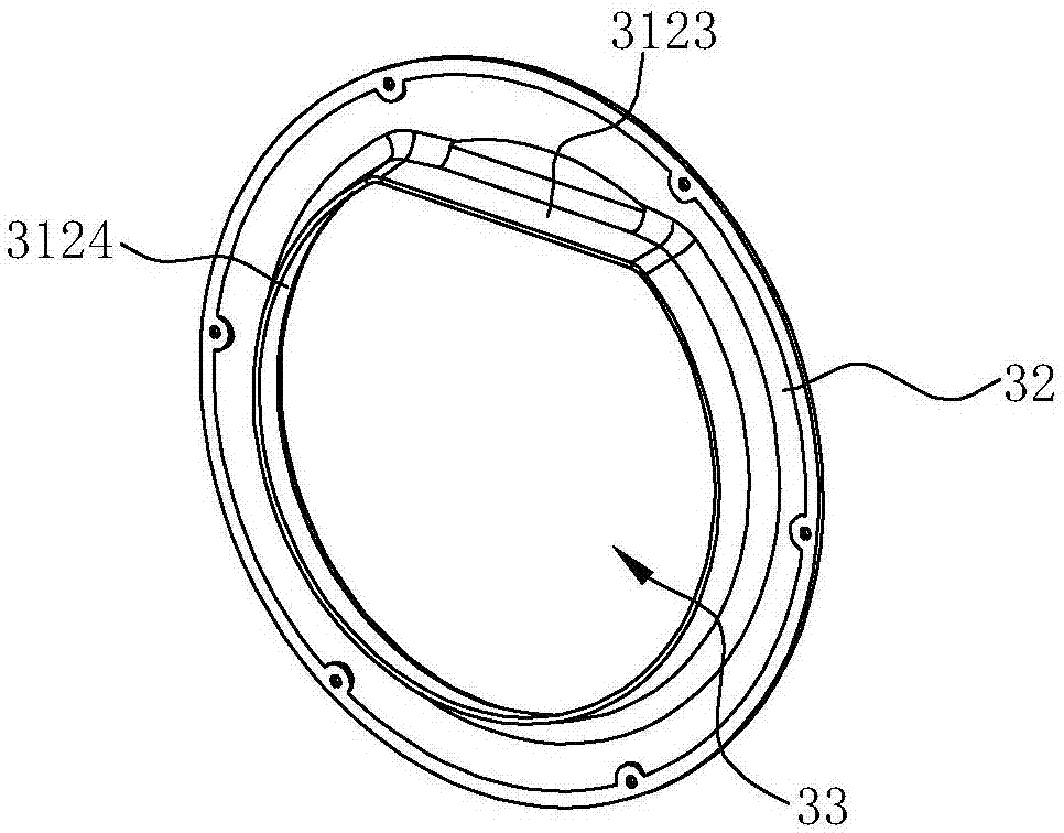
[0025] The collector ...


PUM


Abstract

The invention discloses a current collector, which comprises a wind guide surface and a fixed surface, the fixed surface is in the shape of a ring, the wind guide surface includes a radial wind guide surface extending a certain distance in the radial direction from the radial inner side of the fixed surface, and The radial inner side of the radial air guide surface is an axial wind guide surface extending a certain distance in the axial direction. The middle of the air guide surface is formed as an air inlet. The axial wind guide surface has a first end and a second end in the circumferential direction. The axial wind guide surface Between the first end and the second end are a straight first air guide section and an arc-shaped second air guide section respectively, and the first air guide section and the second air guide section form a closed ring. Also disclosed is a centrifugal fan applied with the collector as described above. Cut a straight line across the air inlet of the collector, and the cross-cut part is close to the volute tongue of the volute, so that the air intake at the volute tongue is reduced, and the flow space at the volute tongue is increased, which reduces the bad flow at the volute tongue The oil fume flow, and the increased space increases the buffer space for the impact of the oil fume flow.

Description

technical field [0001] The invention relates to a range hood, in particular to a centrifugal fan for the range hood and a current collector for the centrifugal fan. Background technique [0002] Household range hoods use a centrifugal fan to extract the oily air out of the kitchen and discharge it to the public flue or directly to the outside. The role of the device is to smoothly guide the fluid to the impeller. The use of current collectors can effectively improve the performance of the fan. At this time, the flow rate of the fan is relatively large, and the noise value is low when working under the design conditions. [0003] Because the type of centrifugal fan commonly used in range hoods is a multi-blade centrifugal fan, its volute is an asymmetrical logarithmic helix shape, so the flow field of the volute is also asymmetrically distributed. Generally, current collectors are designed to be symmetrical in a circular shape, such as a multi-blade centrifugal fan with a m...

Claims


Application Information

Patent Timeline
IPC IPC(8): F04D29/42F04D29/66F24C15/20
CPCF04D29/4206F04D29/663F24C15/20
Inventor 李年平王军元贾博贤茅忠群诸永定
Owner NINGBO FOTILE KITCHEN WARE CO LTD
Why Eureka
Try Eureka