Low-temperature pyrolysis method and system

A low-temperature pyrolysis and pyrolysis furnace technology, which is applied in the petroleum industry, coking ovens, etc., can solve problems such as uncontrollable dioxin generation, and achieve the effects of avoiding excessive flue gas temperature, eliminating open flames, and having fault tolerance

Active Publication Date: 2021-10-19
上海固类特环境科技有限公司
View PDF4 Cites 1 Cited by
  • Summary
  • Abstract
  • Description
  • Claims
  • Application Information

AI Technical Summary

Problems solved by technology

[0006] The purpose of the present invention is to overcome the technical deficiencies of the existing pyrolysis technology that produces open flames and cannot control the generation of dioxins, and provides a low-temperature method that reduces the generation of dioxins. Pyrolysis method to achieve accurate control of flue gas temperature, avoid open flames, and control the generation of dioxins

Method used


Image

  • Low-temperature pyrolysis method and system
  • Low-temperature pyrolysis method and system
  • Low-temperature pyrolysis method and system

Examples


Embodiment 1

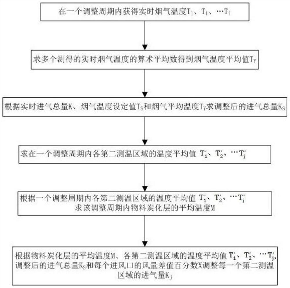
[0047] A low-temperature pyrolysis method according to a preferred embodiment of the present invention, which adjusts the pyrolysis furnace by controlling the total amount of intake air of the pyrolysis furnace and the intake air volume of each area in the pyrolysis furnace according to the temperature of different regions in the pyrolysis furnace The temperature field of the material in the pyrolysis furnace forms a dynamic control to realize the pyrolysis of the material in the pyrolysis furnace without open flame and the control of the flue gas temperature. In this embodiment, the total amount of intake air and the intake air volume of each area are controlled by the temperature of different areas in the pyrolysis furnace, and the obtained temperature in different areas of the pyrolysis furnace can have a complete and comprehensive effect on the thermal field in the pyrolysis furnace. The overall understanding and overall control can determine whether to increase or decrease...

Embodiment 2

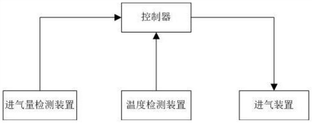
[0092] Such as image 3 As shown, this embodiment provides a low-temperature pyrolysis system for implementing the method of Embodiment 1, including a pyrolysis furnace, a temperature detection device, an air intake device, an intake air volume detection device and a controller, and the temperature detection device is used to detect heat The temperature of different areas in the pyrolysis furnace. The air intake device is used to deliver gas to different areas in the pyrolysis furnace. The temperature detection device, the air intake device and the intake air volume detection device are connected in communication; the controller is used to receive the temperature information of different areas in the pyrolysis furnace detected by the temperature detection device and the temperature information of different areas in the pyrolysis furnace detected by the intake air volume detection device. The intake air volume information, and the total intake air volume is obtained according t...


PUM


Abstract

The invention discloses an open-flame-free low-temperature pyrolysis technology. According to the temperature of different areas in a pyrolyzing furnace, dynamic control is formed by controlling the total gas inlet amount of the pyrolyzing furnace and the gas inlet amount of each area in the pyrolyzing furnace and adjusting the temperature field of materials in the pyrolyzing furnace, and open-fire-free pyrolysis of the materials in the pyrolyzing furnace and control over the flue gas temperature are achieved, so that local high temperature can be avoided, open fire can be eradicated, open-fire-free pyrolysis is achieved, all the areas are kept in approximately the same reaction process, and the material treatment efficiency is improved. The flue gas temperature is effectively controlled, so that the phenomenon that dioxin is generated due to the fact that the flue gas temperature is too high due to the local high temperature is avoided; and meanwhile, the total gas inlet amount is distributed to all the areas, so that the phenomenon that fly ash containing copper ions is generated due to the large gas inlet amount of the local area and reacts with the flue gas to generate dioxin is avoided.

Description

technical field [0001] The invention relates to the technical field of low-temperature pyrolysis, in particular to a low-temperature pyrolysis method and system. Background technique [0002] Pyrolysis is the process of heating substances containing organic combustibles under oxygen-deficient or completely anaerobic conditions to break the chemical bonds of organic substances and produce small molecular substances (gas and liquid) and solid residues. Through the pyrolysis of solid waste, fuel oil, grease and fuel gas can be extracted from it. The application of pyrolysis technology to treat waste has higher energy utilization efficiency and lower secondary pollution emissions, and is considered to be the next generation of waste thermochemical treatment technology for waste incineration technology. [0003] According to the operating temperature of the pyrolysis process, it can be divided into low temperature, medium temperature and high temperature pyrolysis. The pyrolysis...

Claims


Application Information

Patent Timeline
Patent Type & Authority Applications(China)
IPC IPC(8): C10B57/14
CPCC10B57/14
Inventor 彭文博姚文波舒晓波
Owner 上海固类特环境科技有限公司
Why Eureka
Try Eureka