
Torque booster device, method and breast machine

A technology of power-assisted device and force-applying mechanism, which is applied in mammography, mechanical equipment, and balanced rotating body, etc. It can solve problems such as unbalanced rotation, achieve the effect of maintaining balance, improving precision, and reducing requirements

Active Publication Date: 2019-08-16
BEIJING NEUSOFT MEDICAL EQUIP CO LTD
View PDF7 Cites 0 Cited by
  • Summary
  • Abstract
  • Description
  • Claims
  • Application Information

AI Technical Summary

Problems solved by technology

[0012] In view of this, the present application provides a torque booster, a method and a mammary gland machine to solve the problem in the prior art that the torque generated by the gravity of the rigid part rotates around the axis, resulting in unbalanced rotation

Method used


Image

  • Torque booster device, method and breast machine
  • Torque booster device, method and breast machine
  • Torque booster device, method and breast machine

Examples


Embodiment 1

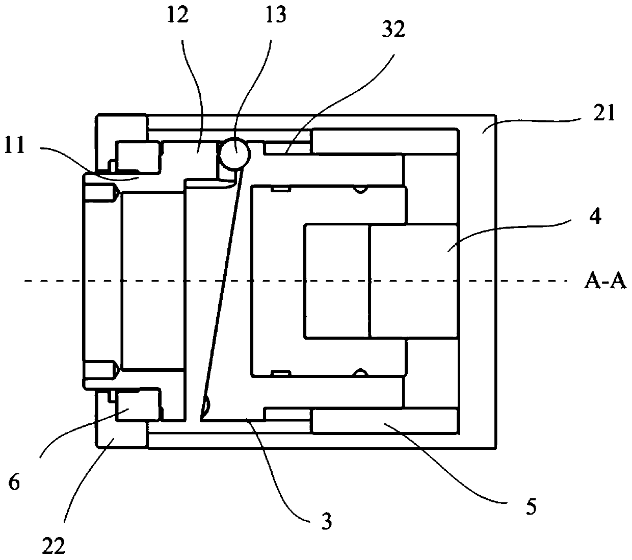
[0055] figure 2 A cross-sectional view of a torque booster provided in this embodiment. The torque assist device can be used in mammary gland machines to counteract the torque M generated by the gravity of the rotating parts when the rotating parts of the mammary gland machine rotate around the axis. G , so as to assist the rotating member to always rotate around a fixed axis.

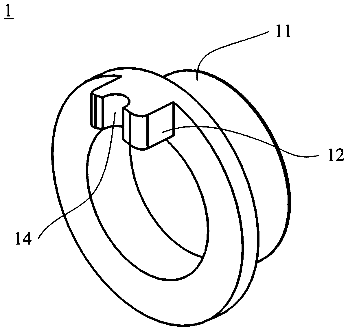
[0056] like figure 2 and Figure 4 to Figure 6 As shown, the torque booster includes a rotating mechanism 1 , a fixed cylinder 3 and a force applying mechanism 4 . Wherein, the rotating mechanism 1 is provided with a load (not shown in the figure). One end surface of the fixed cylinder 3 is provided with a motion track 31 with an inclination angle, and the inclination angle of the motion track 31 is set according to the torque generated by the gravity of the load. And the fixing cylinder 3 is connected with the force applying mechanism 4 . Optionally, one end of the fixed cylinder 3 is provided w...

Embodiment 2

[0122] Thanks to M F It is generated by relative motion, so the trajectory of relative motion and the position of the steel ball can be interchanged. For example, set the motion trajectory on the rotating part, and set the steel ball on the fixed cylinder, such as Figure 15 Shown is a cross-sectional view of the torque booster provided in this embodiment.

[0123] Please combine Figure 15 to Figure 17 , another torque booster device provided by the present application includes a rotating mechanism 1', a fixed cylinder 3' and a force applying mechanism 4'. Wherein, the rotating mechanism 1' is provided with a load (not shown in the figure), and one end of the rotating mechanism 1' is provided with a motion track 12' with an inclination angle, and the inclination angle of the motion track 12' is according to the The torque setting produced by the weight of the load. The fixed cylinder 3 ′ abuts on the motion track 12 ′, and the fixed cylinder 3 ′ is connected with the forc...


PUM


Abstract

A torque assisting device, a method and a mammary machine are provided. According to an example, the torque assisting device includes a rotating mechanism, a fixing cylinder and an axially elastic force-applying mechanism. The rotating mechanism is provided with a load. An end surface of the fixing cylinder is provided with a motion trajectory having an inclination angle and the fixing cylinder is connected with the force-applying mechanism. The rotating mechanism is abutted on the motion trajectory at one end thereof and rotates about an axis of rotation along the motion trajectory. The inclination angle of the motion trajectory is set according to a torque generated by the gravity of the load. By setting the motion trajectory with an inclination angle and the fixing cylinder, torque associated with rotation angle of the centre of gravity of the load may be output passively, counteracting the torque generated by the load's gravity.

Description

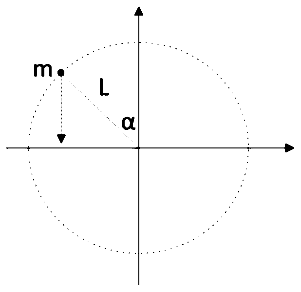
technical field [0001] The present application relates to the field of torque balance, in particular to a torque boosting device, method and mammary gland machine in medical equipment. Background technique [0002] When a rigid load rotates around an axis, there may be a case where the gravity of the load will generate a torque because the center of gravity of the load does not coincide with the axis of rotation. Both the magnitude and direction of this torque vary with the load's rotation angle and rotation phase. see figure 1 , the mass of the load is m, the radius from its center of gravity to the axis of rotation is L, and the angle between the real-time radius of the rotation of the center of gravity of the load and the vertical direction is α, then the torque M generated by the gravity of the load G : [0003] m G =m×g×L×sinα (1) [0004] where g is the acceleration due to gravity. [0005] From the formula (1), it can be concluded that the magnitude of the torqu...

Claims


Application Information

Patent Timeline
Patent Type & Authority Patents(China)
IPC IPC(8): F16F15/32
CPCF16F15/322A61B6/4429A61B6/502
Inventor 孙俊杰
Owner BEIJING NEUSOFT MEDICAL EQUIP CO LTD
Learn More