Switch transformation installation wth input in low voltage

A switching conversion, low-voltage input technology, applied in the output power conversion device, the conversion of DC power input to DC power output, and the adjustment of electrical variables, etc. The effect of saving design costs and improving cost competitiveness

Inactive Publication Date: 2007-11-28
徐州正兴除尘设备制造有限公司
View PDF3 Cites 0 Cited by
  • Summary
  • Abstract
  • Description
  • Claims
  • Application Information

AI Technical Summary

Problems solved by technology

[0003] In order to take both production and procurement into consideration, two sets of schemes should be used in the design at the same time, resulting in a long R&D cycle and high development costs

Method used


Image

  • Switch transformation installation wth input in low voltage
  • Switch transformation installation wth input in low voltage
  • Switch transformation installation wth input in low voltage

Examples


Embodiment Construction

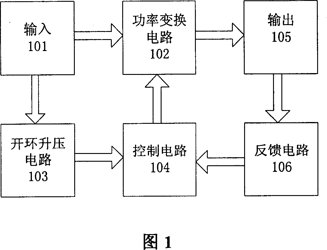
[0021] The low-voltage input switch conversion device disclosed by the present invention is shown in FIG. 1 . It mainly consists of the following parts: an input circuit 101 , a power conversion circuit 102 , an output circuit 105 , a feedback circuit 106 , a control circuit 104 and an open-loop boost circuit 103 . The voltage signal of the input circuit 101 is filtered and then connected to the power conversion circuit 102 for power conversion. At the same time, 101 is connected to the open-loop boost circuit 103 to provide the input voltage. After the open-loop boost circuit 103 boosts the input voltage, it is connected to the control circuit. 104 provides an auxiliary power supply, the control circuit 104 is connected to the power conversion circuit 102 for power conversion, and the power conversion circuit 102 is connected to the output circuit 105 for rectification and filtering and outputs the converted voltage. The output circuit 105 is connected to the feedback circuit...


PUM


Abstract

The installation includes input circuit, power conversion circuit, output circuit, feedback circuit, control circuit and boosted circuit. Voltage signal of input circuit through filtering is connected to power conversion circuit to carry our power conversion. Meanwhile, input circuit is connected to the boosted circuit to provide input voltage. With being raised by the boosted circuit, the input voltage is connected to control circuit to provide auxiliary source. Control circuit is connected to power conversion circuit to carry out power conversion. Power conversion circuit connected to output circuit carrying out rectifying and filtering operations outputs converted voltage. Output circuit connected to feedback circuit provides feedback voltage. Feedback circuit connected to control circuit realizes close loop control in order to meet need at low voltage.

Description

technical field [0001] The invention relates to a low-voltage input isolation / non-isolation module power supply in the field of switching power supplies, in particular to a device capable of realizing low-voltage input switching conversion. Background technique [0002] In the low-voltage input module power supply, because the input voltage is too low (up to 3.0VDC), in order to meet the operating voltage of the control chip and the driving requirements of the power switch tube, it is generally necessary to use a dedicated control chip for conversion and driving. The disadvantages of this conversion method are: (1) The control chips are currently exclusively supplied, which is difficult to purchase and relatively expensive. (2) When using this control chip, when the input voltage is lower than 4VDC, logic must be used to drive the power switching device. [0003] In order to take both production and procurement into consideration, two sets of schemes should be used in the d...

Claims


Application Information

Patent Timeline
Patent Type & Authority Patents(China)
IPC IPC(8): H02M3/145H02M3/156
Inventor 王士民
Owner 徐州正兴除尘设备制造有限公司
Why Eureka
Try Eureka