Supercharge Your Innovation With Domain-Expert AI Agents!

Pneumatic launching canister mechanism for loitering munition

A technology for launching cylinders and missiles, applied in the field of pneumatic launching cylinder mechanisms, can solve the problems of large acceleration overload peak value, complex cylinder processing, inability to adapt to kinematic performance requirements, etc., so as to avoid structural damage and reduce processing difficulty and cost. Effect

Pending Publication Date: 2018-04-27
BEIJING INST OF AEROSPACE TESTING TECH
View PDF5 Cites 2 Cited by
  • Summary
  • Abstract
  • Description
  • Claims
  • Application Information

AI Technical Summary

Problems solved by technology

[0003] This method makes the processing of the cylinder complex; at the same time, after the gas generator is started, the pressure at the lower part of the piston will rise rapidly, resulting in a large acceleration overload peak value, making the structure of the loitering projectile easily damaged; in addition, the overload and the speed of the cylinder during the acceleration process cannot be controlled. Adjustment, unable to adapt to the relevant kinematic performance requirements for take-off of projectiles with different charges

Method used


Image

  • Pneumatic launching canister mechanism for loitering munition

Examples


Embodiment Construction

[0009] Below in conjunction with accompanying drawing, further illustrate the present invention with example.

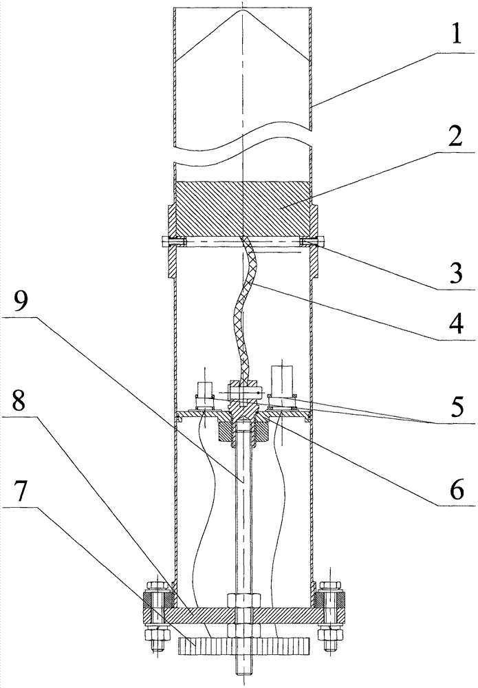
[0010] Such as figure 1 As shown, a pneumatic launching cylinder mechanism includes a cylinder body 1, a piston 2, a flow limiting orifice plate 3, a tether 4, a gas generator 5, an inner bottom plate 6, a controller 7, an outer bottom plate 8, and an adjusting screw 9.

[0011] Before launch, first install the flow-limiting orifice 3 with a suitable aperture, adjust the axial position of the inner bottom plate 6 with the screw thread of the adjustment screw 9 and fix it with the nut, adjust the length of the corresponding tether 4 and fix the two ends of the rope to the piston respectively. 2. On the bottom and the inner bottom plate 6, a start signal is provided to the controller 7, and the two gas generators 5 are started one after another and release the high-pressure gas. The high-pressure gas pushes the piston 2 and the loitering bomb through the flow-limiting ...


PUM


Abstract

The invention provides a pneumatic launching canister structure used for providing an initial speed during launching of loitering munition. The pneumatic launching canister structure comprises a canister body, a piston, a flow-limiting orifice plate, a tying rope, gas generators, an inner bottom plate, a controller, an outer bottom plate and an adjustment lead screw, wherein two gas generators arearranged, and the controller is used for controlling a starting time interval of the two gas generators. The pneumatic launching canister structure provided by the invention has the following beneficial effects: the gas generators are started in succession and release high-pressure gas under the action of the controller after receiving starting signals, the high-pressure gas pushes the piston andthe loitering munition to carry out accelerated movement together through the flow-limiting orifice plate, when the piston moves to the edge of the canister body, the tying rope is tensioned, the piston is separated from the loitering munition under the tension of the tying rope, and rapidly decelerates and stays in a canister, and no overflow of the high-pressure gas is ensured, so that a soundless and lightless launching effect can be realized; in addition, the axial position of the inner bottom plate can be adjusted through the adjustment lead screw, the inside capacity of a launching cavity is changed, and then the effect of changing a launching speed is achieved; and a gas release speed can be controlled through changing the orifice diameter of the flow-limiting orifice plate, and then the effect of changing an overload during launching is achieved.

Description

technical field [0001] The invention relates to a pneumatic launch tube mechanism, which can provide an initial velocity for a loitering bomb when it takes off, and is applicable to the technical field of a catapult take-off loitering bomb and loitering bomb. Background technique [0002] The loitering bomb is a new concept ammunition that can perform "cruising flight" and "standby attack target" above the target area, and has the ability to integrate reconnaissance and strike. Once this new attack method was proposed, it has attracted the attention of many countries. The United States, Russia, Britain, Germany, France and other countries have carried out research on it. The research on the mechanism of the pneumatic launcher of the loitering bomb is as follows: the American switchblade launcher has three layers, which are Kevlar, light base material, and Kevlar from the inside to the outside; the gas released by the gas generator is high-temperature gas , and directly push...

Claims


Application Information

Patent Timeline
IPC IPC(8): F41F1/00
CPCF41F1/00
Inventor 罗天培李茂张家仙尹奇志王成刚孙凤伟刘瑞敏张佳尚凯伦孔凡超李伟乐
Owner BEIJING INST OF AEROSPACE TESTING TECH
Features
  • R&D
  • Intellectual Property
  • Life Sciences
  • Materials
  • Tech Scout
  • Unparalleled Data Quality
  • Higher Quality Content
  • 60% Fewer Hallucinations
Learn More