
An angle adjustment platform and adjustment method driven by normal electromagnetic stress

A technology of electromagnetic stress and angle adjustment, applied in the direction of electromagnets, electromagnets with armatures, magnets, etc., can solve the problems affecting the overall performance of the system, small angle adjustment range, small frequency band range, etc., to improve the adjustment accuracy and frequency range. Large, responsive effects

Active Publication Date: 2021-05-04
西安朗威科技有限公司
View PDF15 Cites 0 Cited by
  • Summary
  • Abstract
  • Description
  • Claims
  • Application Information

AI Technical Summary

Problems solved by technology

The traditional angle adjustment mechanism is mainly divided into piezoelectric drive and voice coil motor drive according to different driving methods. The piezoelectric drive is characterized by high operating frequency and wide bandwidth range, but the angle adjustment range is small, and a displacement amplification mechanism is needed to expand the angle adjustment. Range, and high power consumption; the voice coil motor drive is to use the electric wire to cut the magnetic field to generate ampere force to push the deflection mechanism, which is characterized by large driving force and large angle adjustment range, but limited by the rigidity of the structural support, the frequency range is small, and The control current increases with the increase of the pointing angle range, and the coil generates a lot of heat, which affects the overall performance of the system

Method used


Image

  • An angle adjustment platform and adjustment method driven by normal electromagnetic stress
  • An angle adjustment platform and adjustment method driven by normal electromagnetic stress

Examples


Embodiment Construction

[0019] The present invention will be described in further detail below in conjunction with the accompanying drawings and specific embodiments.

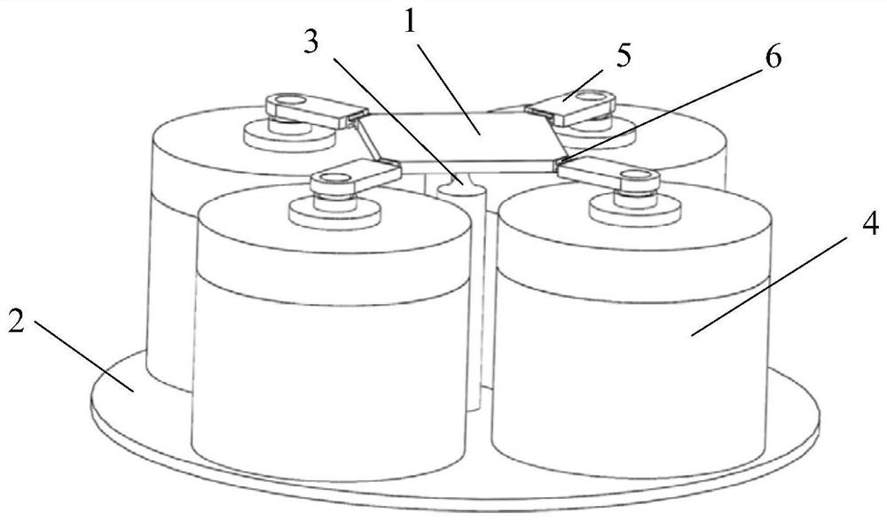
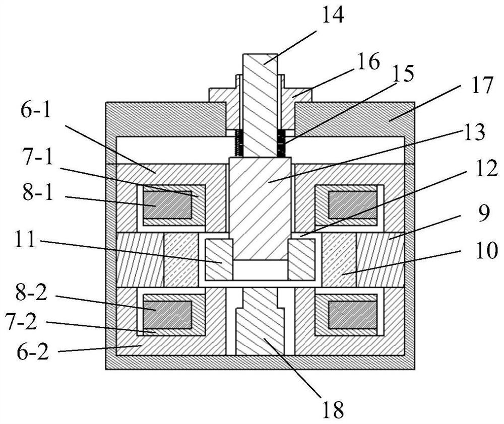
[0020] Such as figure 1 As shown, an angle adjustment platform driven by normal electromagnetic stress in the present invention includes a moving platform 1 , a fixed platform 2 , and a universal flexible hinge support 3 connecting the moving platform 1 and the fixed platform 2 . The moving platform 1 is connected with four normal electromagnetic stress drivers 4 through a straight beam type flexible hinge 6 and a connecting bracket 5 . The four normal electromagnetic stress drivers 4 are installed on the fixed platform 2 through bolts, and are symmetrical to the universal flexible hinge support 3, and are distributed in pairs diagonally. The normal electromagnetic stress driver 4 is connected with the connecting bracket 5 through the actuating rod 14 . The two diagonally distributed normal electromagnetic stress drivers 4 output dr...


PUM


Abstract

An angle adjustment platform driven by normal electromagnetic stress and an adjustment method thereof, the angle adjustment platform includes a moving platform, a fixed platform, a universal flexible hinge support, a straight beam type flexible hinge and four normal electromagnetic stress drivers; the four drivers are fixed On the fixed platform, it is distributed in pairs diagonally around the universal flexible hinge support; the upper end of the driver is connected to the connecting bracket through the guide support rod, and the connecting bracket is connected to the moving platform through a straight beam type flexible hinge; the driver includes a fixed iron core , coil bobbin, excitation coil, permanent magnet and moving iron core; the permanent magnet generates a bias magnetic field, which is energized to generate an exciting magnetic field, which is superimposed with the bias magnetic field to generate electromagnetic stress, which acts on the moving iron core together to make it move vertically direction movement, the two drivers arranged diagonally act together to push the moving platform to rotate in the diagonal direction; at the lower end of the moving iron core inside the driver, a capacitive displacement sensor is arranged to collect the moving displacement of the moving iron core along the vertical direction signal; the present invention can realize the high-precision deflection control of the pointing angle.

Description

technical field [0001] The invention relates to the technical field of pointing angle adjustment control, and specifically designs an angle adjustment platform and an adjustment method driven by normal electromagnetic stress. Background technique [0002] Pointing angle adjustment mechanisms are widely used in aerospace, ultra-precision machinery manufacturing, micro-electromechanical engineering, optical systems and other fields. The traditional angle adjustment mechanism is mainly divided into piezoelectric drive and voice coil motor drive according to different driving methods. The piezoelectric drive is characterized by high operating frequency and wide bandwidth range, but the angle adjustment range is small, and a displacement amplification mechanism is needed to expand the angle adjustment. Range, and high power consumption; the voice coil motor drive is to use the electric wire to cut the magnetic field to generate ampere force to push the deflection mechanism, which...

Claims


Application Information

Patent Timeline
Patent Type & Authority Patents(China)
IPC IPC(8): G05D3/12F16M11/08F16M11/18F16M11/20H01F7/16
CPCF16M11/08F16M11/18F16M11/2014G05D3/12H01F7/1638
Inventor 张丰徐明龙田征马国亮
Owner 西安朗威科技有限公司
Learn More