
Lubricating oil regenration apparatus and method

A technology of lubricating oil and lubricating oil tank, which is applied in the directions of lubricating oil distillation, chemical instruments and methods, separation methods, etc., and can solve problems such as lubricating performance degradation

Inactive Publication Date: 2018-05-01
HYUNDAI MOTOR CO LTD
View PDF7 Cites 1 Cited by
  • Summary
  • Abstract
  • Description
  • Claims
  • Application Information

AI Technical Summary

Problems solved by technology

In this way, if the working fluid introduced into the lubricating oil is not separated, the lubricating performance may decrease, and the working fluid may overflow the lubricating oil tank beyond the storage capacity of the lubricating oil tank

Method used


Image

  • Lubricating oil regenration apparatus and method
  • Lubricating oil regenration apparatus and method
  • Lubricating oil regenration apparatus and method

Examples


Embodiment Construction

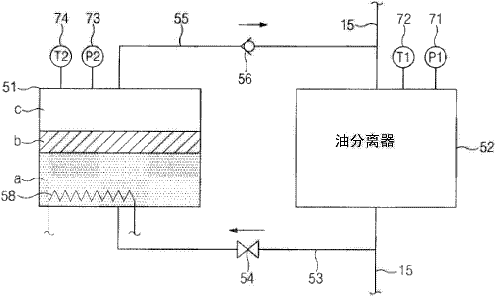
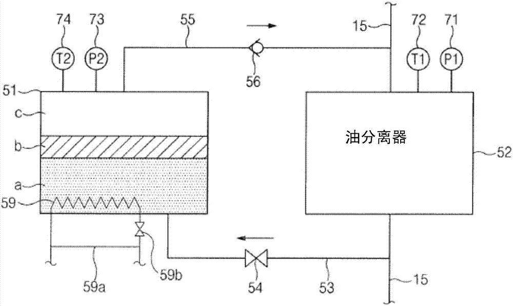
[0032] Hereinafter, embodiments of the present invention will be described in detail with reference to the accompanying drawings. For reference, the size of components, the thickness of lines, etc. shown in the drawings used to describe the exemplary embodiments of the present disclosure may be slightly exaggerated for ease of understanding. Further, terms used to describe the present disclosure may be defined in consideration of functions in the present disclosure and thus may be changed according to users' and operators' intentions, practices, and the like. Therefore, the definitions of terms should be interpreted based on the contents of the entire specification.

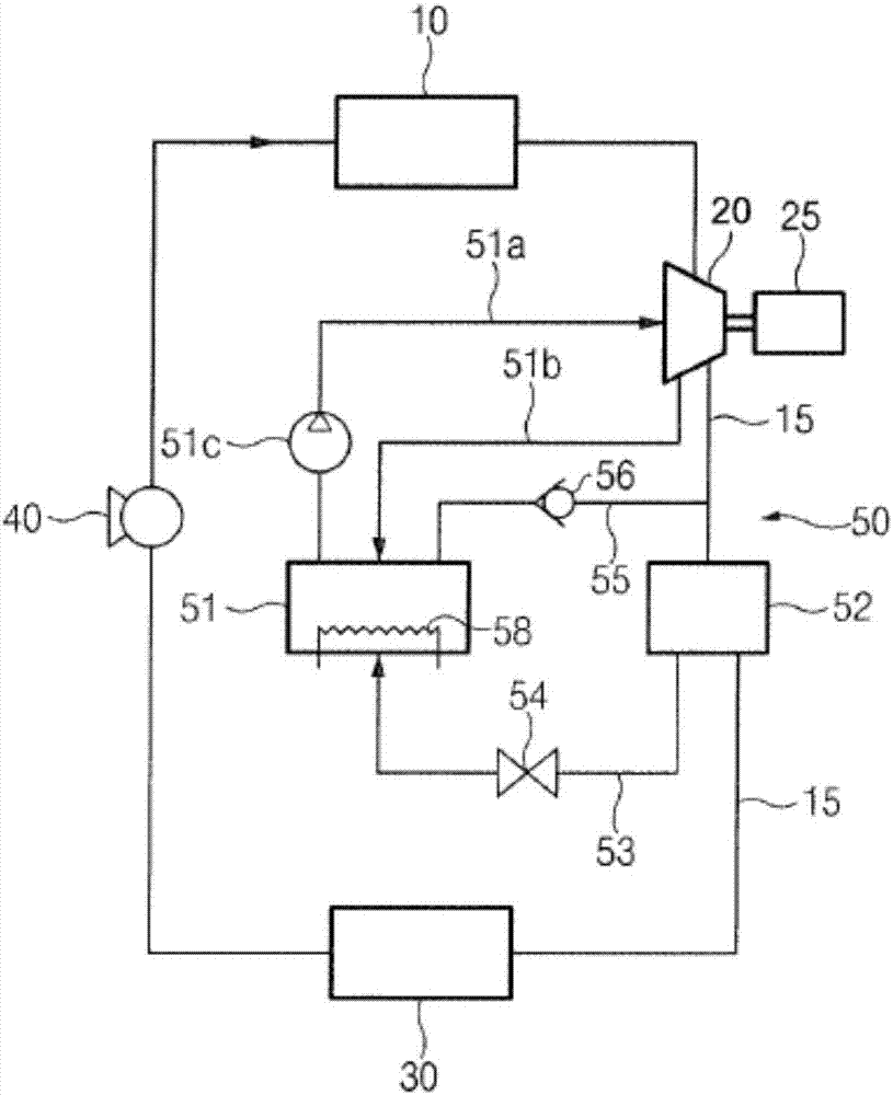
[0033] figure 1 is a diagram showing an example of a general waste heat recovery system.

[0034] refer to figure 1 , the waste heat recovery system may include a working fluid pipe 15 through which a working medium is circulated, wherein the working fluid pipe 15 may include: a boiler 10 configured to pass en...


PUM


Abstract

The invention provides an apparatus comprising a lubricating oil tank storing a lubricating oil. An oil separator separates the lubricating oil from a working fluid discharged from an expander of a waste heat recovery system. A lubricating oil return conduit is connected between the oil separator and the lubricating oil tank. A working fluid return conduit is connected between the lubricating oiltank and the oil separator. A vaporizer unit is installed in the lubricating oil tank to vaporize a liquefied working fluid mixed with the separated lubricating oil in the lubricating oil tank.

Description

[0001] Cross References to Related Applications [0002] This application is based upon and claims the benefit of Korean Patent Application No. 10-2016-0138716 filed with the Korean Intellectual Property Office on October 24, 2016, the disclosure of which is incorporated herein by reference in its entirety. technical field [0003] The present disclosure relates to an apparatus and method for regenerating lubricating oil, and more particularly, to an apparatus and method for regenerating lubricating oil capable of improving the lubricating properties of the lubricating oil by effectively separating the lubricating oil from the working fluid. performance and the heat exchange performance of the working fluid. Background technique [0004] Internal combustion engines have been widely used in vehicles, ships, small generators, etc. and attempts to improve the efficiency of the internal combustion engines have been continuously made. In internal combustion engines, a large amou...

Claims


Application Information

Patent Timeline
IPC IPC(8): C10M175/00C10N40/25
CPCC10M175/0091C10N2040/25B01D17/0208B01D17/042C10M175/0033C10G7/003C10G7/12C10G2300/1062C10G2300/4006B01D1/0058B01D1/0082
Inventor 徐正玟
Owner HYUNDAI MOTOR CO LTD
Learn More