Speed reducing and energy recycling equipment

A technology of energy recovery and equipment, which is applied in the direction of roads, road signs, traffic signals, etc., can solve the problems of poor recovery effect, no safety prevention and control devices, no speed bumps, etc., and achieve high energy recovery and utilization efficiency. Conducive to the effect of smooth passage and convenient flow control

Pending Publication Date: 2018-05-01
大连函量科技发展有限公司
View PDF6 Cites 4 Cited by
  • Summary
  • Abstract
  • Description
  • Claims
  • Application Information

AI Technical Summary

Problems solved by technology

However, the setting of the deceleration belt also makes the motor vehicle decelerate while losing a certain amount of energy. Therefore, it is very necessary to set a system device that can be used as a deceleration belt on the road surface and can recover energy. However, the existing deceleration and Most of the energy recovery equipment is installed on the road, and most of them use airbags to compress and collect

Method used


Image

  • Speed reducing and energy recycling equipment
  • Speed reducing and energy recycling equipment
  • Speed reducing and energy recycling equipment

Examples


Embodiment 1

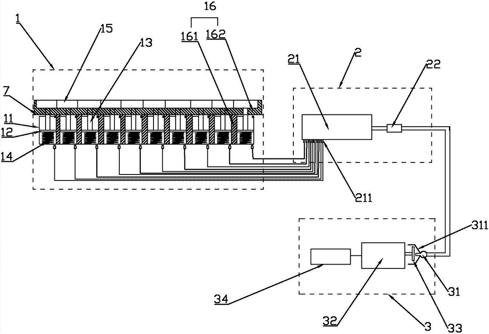
[0029] Such as figure 1 with figure 2 As shown, a deceleration and energy recovery equipment, including an inflator 1 and a gas storage device 2,

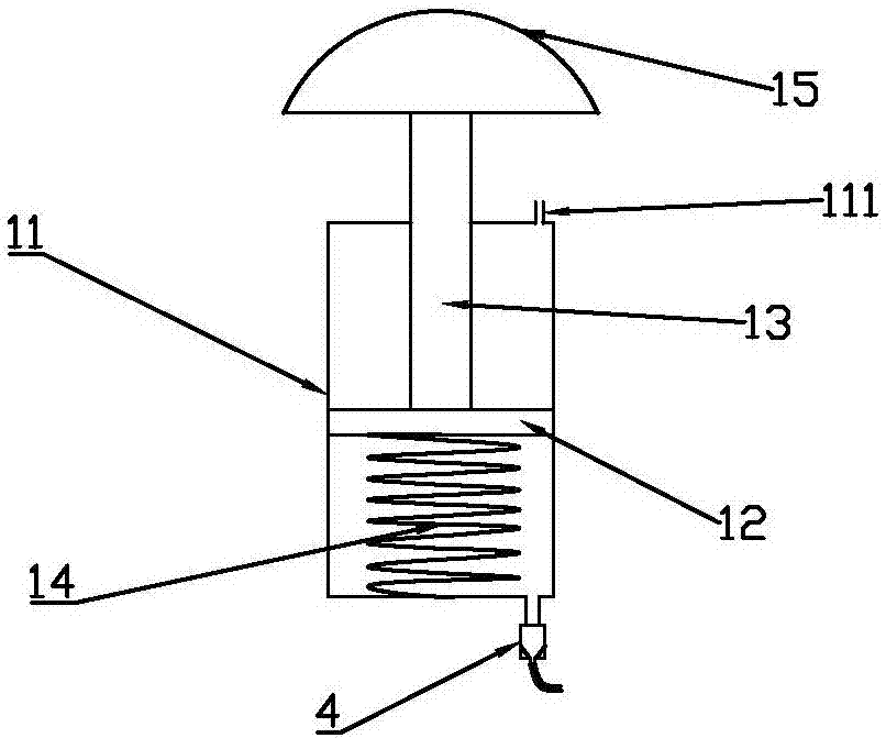
[0030] The inflatable device 1 includes a cylinder 11, a piston 12, a piston rod 13, a return spring 14, a contact head 15 and a rubber belt 16. A piston rod guide hole is arranged in the middle of the upper end of the cylinder 11, and an air hole 111 is arranged on one side of the upper end of the cylinder 11. , the lower end of the cylinder 11 is conductively connected to the one-way valve 4, a plurality of the cylinders 11 are arranged side by side in the foundation pit under the road surface, the piston 12 is slidably connected in the cylinder 11, and the lower end of the piston rod 13 is connected to the The upper end of the piston 12 is fixedly connected, the upper end of the piston rod 13 passes through the piston guide hole and is fixedly connected to the middle part of the lower end of the contact head 15, and the lower ...

Embodiment 2

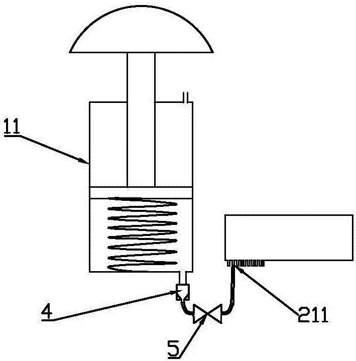
[0042] Such as image 3 As shown, the difference between this embodiment and Embodiment 1 lies in that a control valve 5 is also provided between the one-way valve 4 and the air collecting hole 211 .

[0043] Further, in the above technical solution, the control valve 5 is an electric valve or a solenoid valve.

[0044] The control valve 5 is used to adjust or close the gas outflow in the conduit or block the gas compressed by the cylinder 11 for convenient control.

Embodiment 3

[0046] Such as Figure 4 As shown, the difference between this embodiment and Embodiment 1 is that the height of the deceleration belt 162 and the contact head 15 decreases continuously from the entry end to the exit end.

[0047] Further, in the above technical solution, the contact head 15 is closely matched with the speed reduction belts 162 on both sides.

[0048]By adopting this structure, the vibration received when the motor vehicle passes is greatly reduced.


PUM


Abstract

The invention discloses speed reducing and energy recycling equipment which comprises an aeration device and an air storage device. The aeration device comprises air cylinders, pistons, piston rods, reset springs, contact heads and a rubber belt. The air cylinders are arranged in foundation pits below a road surface side by side, the upper ends of the pistons penetrate through piston guide holes to be fixedly connected with the middles of the lower ends of the contact heads, and the lower ends of the reset springs are fixedly connected to the bottoms of inner cavities of the air cylinders. Theupper ends of the reset springs are fixedly connected with the lower ends of the pistons, and the rubber belt comprises integrally connected auxiliary belts and speed reducing belts mounted on the two sides of the contact heads. The air storage device comprises an air storage tank and a buffer valve, and the right side of the air storage tank is in communicated connection with the air inlet end of the buffer valve. The speed reducing and energy recycling equipment is reliably mounted below the road surface and has diversified functions.

Description

technical field [0001] The invention belongs to the technical field of energy recovery and utilization, and in particular relates to a deceleration and energy recovery device. Background technique [0002] Energy recovery is to convert the lost energy into usable energy through certain equipment. The speed bump is a traffic facility installed on the road to slow down the passing vehicles, so that the road surface is slightly arched to achieve the purpose of vehicle deceleration. Usually set At highway crossings, industrial and mining enterprises, schools, entrances to residential quarters, steep downhill slopes and other road sections that require vehicles to slow down and road sections that are likely to cause traffic accidents, it is a new traffic-specific safety setting for slowing down the speed of motor vehicles and non-motor vehicles. However, the setting of the deceleration belt also makes the motor vehicle decelerate while losing a certain amount of energy. Therefore...

Claims


Application Information

Patent Timeline
IPC IPC(8): E01F9/529
CPCE01F9/529
Inventor 韩亮
Owner 大连函量科技发展有限公司
Why Eureka
Try Eureka