Deformation joint processing structure of top plate

A deformation joint and roof technology, which is applied in building components, building structures, building insulation materials, etc., to reduce adverse effects, prevent rainwater from infiltrating into deformation joints, and achieve good structural performance.

Inactive Publication Date: 2018-05-01
俞岳峰
View PDF0 Cites 5 Cited by
  • Summary
  • Abstract
  • Description
  • Claims
  • Application Information

AI Technical Summary

Problems solved by technology

[0003] The purpose of the present invention is to solve the defects existing in the deformation joint structure in the prior art, and provide a roof deformation jo

Method used


Image

  • Deformation joint processing structure of top plate
  • Deformation joint processing structure of top plate

Examples


Embodiment Construction

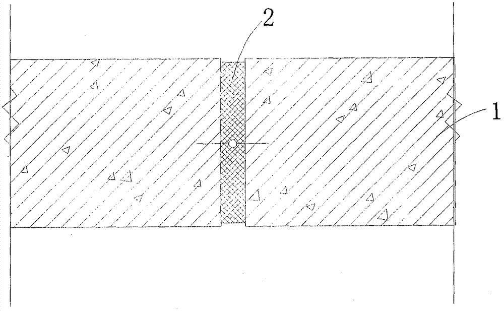
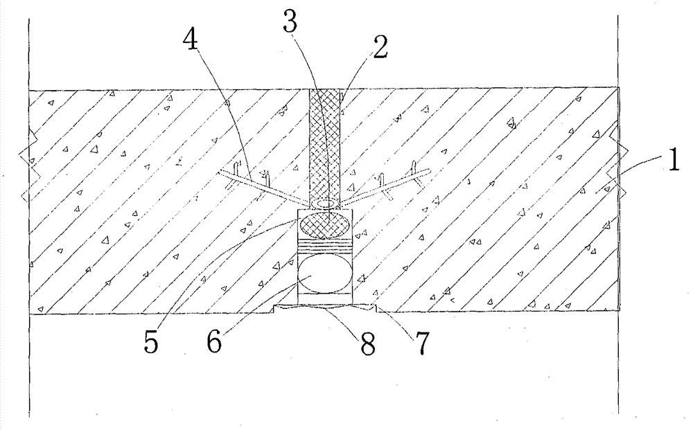
[0012] Such as figure 1 , figure 2 As shown, a concrete structure deformation joint treatment includes a concrete structure layer 1, a deformation joint 2 is arranged on the concrete structure layer 1, a gap grouting cavity 4 that is chiseled wide is provided at one end of the deformation joint 2, two ends of the deformation joint 2 The side connection grouting tank pumping pipe cavity 5, the gap grouting cavity 5 is sealed by leaking treasure and epoxy putty, and the non-curing liquid rubber glue waterstop 3 is poured into the gap grouting cavity 5.

[0013] Further, in the concrete structure layer 1, the pre-embedded grouting pipe 6 is located in the middle of the deformation joint 2, and the two sides of the deformation joint 2 have a made concrete shoulder shape 7, and the deformation joint 2 is located at the concrete shoulder shape 7. A W-shaped The stainless steel plate 8 and the W-shaped stainless steel plate 8 are sealed by polyurethane or thixotropic polysulfide se...


PUM


Abstract

The invention relates to a deformation joint processing structure of a top plate. The deformation joint processing structure comprises a concrete structure layer equipped with a deformation joint. Oneend of the deformation joint is provided with a joint grouting cavity which is chiseled. The joint grouting cavity is internally poured with a non-solidified liquid rubber water-stop belt. Two sidesof the deformation joint are connected with grouting slot drawing pipe cavities. The joint grouting cavity is sealed by an anti-seepage product and epoxy putty. The deformation joint processing structure has good water-proof performance. Additionally, structure performance is excellent. The protection effect is very evident and capable of effectively preventing rainwater from seeping into the deformation joint. The anti-deformation capability is high. Therefore, adverse influence of the earth surface upon the deformation joint is effectively reduced.

Description

technical field [0001] The invention relates to a roof deformation seam treatment structure. Background technique [0002] The main purpose of the deformation joint is to absorb or buffer the stress of the structure due to factors such as temperature difference, settlement and vibration, so it needs to be prevented to avoid cracking or damage to the concrete structure so that it does not affect the structure of the building. A well-designed deformation joint can effectively prevent many problems, not just preventing the infiltration of rainwater. However, the general deformation joint has a single structure and function, and its own structure is unstable, which may cause the crack to be too wide, so it cannot be achieved. The effect of the deformation joint itself will cause damage to the wall in serious cases, and phenomena such as dumping will occur. It cannot better achieve the effect it should achieve, and its functionality is poor. Contents of the invention [0003] ...

Claims


Application Information

Patent Timeline
IPC IPC(8): E04B1/66E04B1/68
CPCE04B1/66E04B1/68E04B1/6806
Inventor 俞岳峰俞逍
Owner 俞岳峰
Why Eureka
Try Eureka