Heat storage device and system

A technology of heat storage device and heat storage system, which is applied in the field of solar heat storage, and can solve problems such as unstable operation of the system, reduced efficiency, and aggravated local turbulent flow at the inlet and outlet

Inactive Publication Date: 2018-05-01
GLOBAL ENERGY INTERCONNECTION RES INST EURO GMBH +1
View PDF2 Cites 9 Cited by
  • Summary
  • Abstract
  • Description
  • Claims
  • Application Information

AI Technical Summary

Problems solved by technology

[0006] Therefore, the technical problem to be solved by the embodiments of the present invention lies in the thermal slope layer-based heat storage method using sensible heat storage in the prior art. The single-tank heat storage will intensify the local turbulence at the inlet and outlet, which will reduce the efficiency of the system and lead to unstable operation of the system

Method used


Image

  • Heat storage device and system
  • Heat storage device and system
  • Heat storage device and system

Examples


Embodiment 1

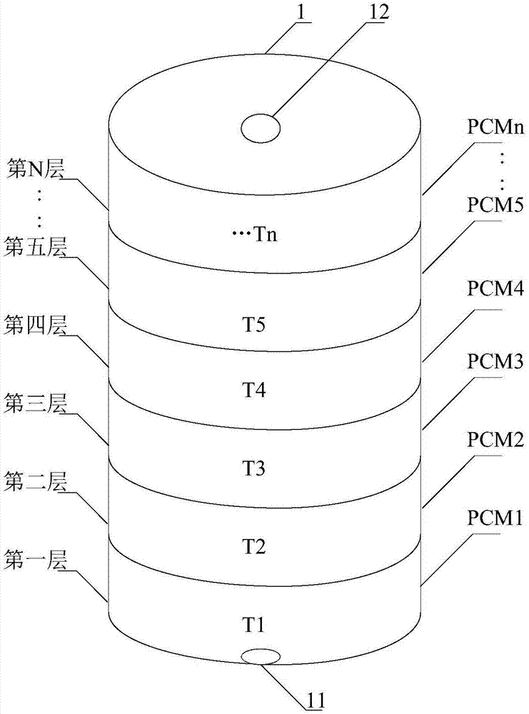
[0040] An embodiment of the present invention provides a heat storage device used in a heat storage system, such as figure 1 As shown, it includes a heat storage tank 1 for heat storage, and the heat storage tank 1 is a cylindrical heat storage tank. The tank diameter and height of the heat storage tank 1 mainly depend on the heat storage temperature and storage temperature. Heat capacity, the heat storage tank body 1 is a cylinder. Both sides of the heat storage tank body 1 are respectively provided with a heat input port 11 and a heat output port 12, and a multi-layer phase change material is arranged in the heat storage tank body 1, which are respectively PCM1, PCM2, PCM3, PCM4, PCM5, ... PCMn , between the heat input port 11 and the heat output port 12, a channel for heat transfer medium circulation is formed through the gap of the multi-layer phase change material, and the phase change temperature of each layer of phase change material increases gradually along the direct...

Embodiment 2

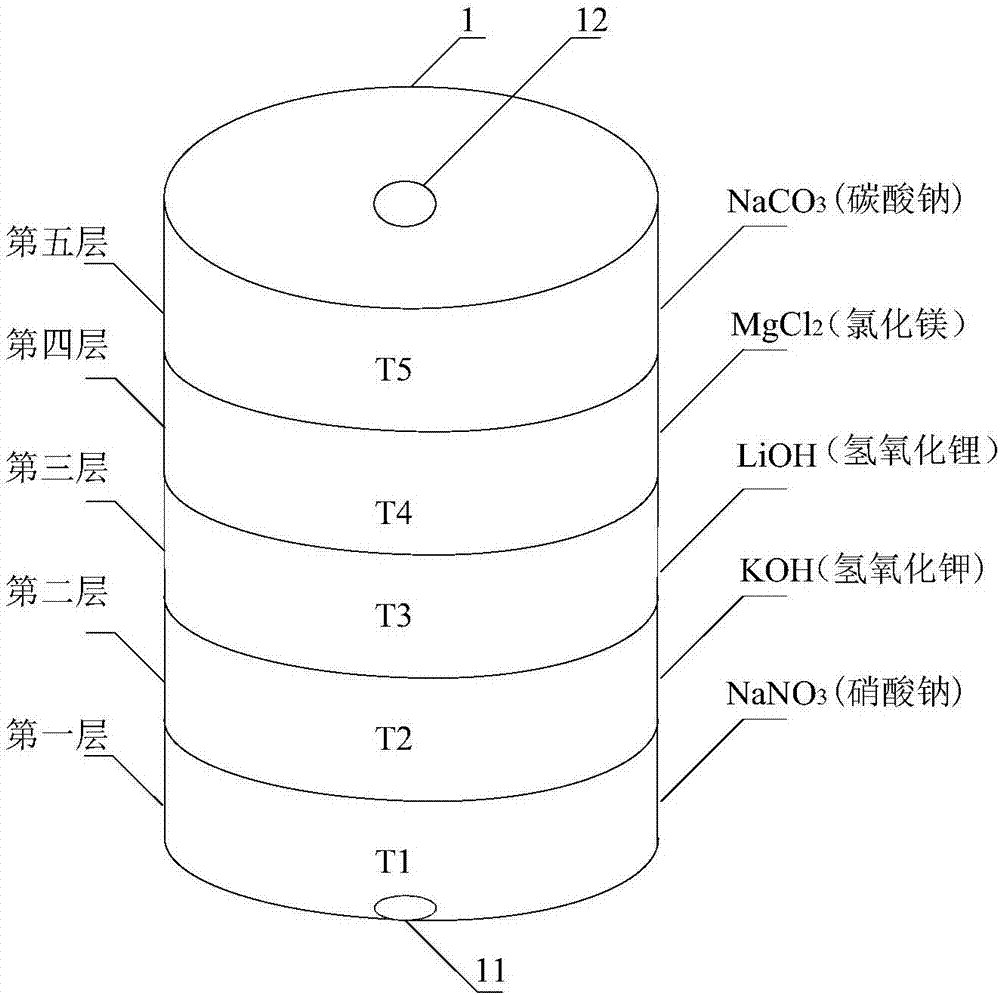
[0055] An embodiment of the present invention provides a heat storage device, such as Figures 3A-3EShown are heat storage devices composed of phase change materials with five structures. It includes a heat storage tank 1 for heat storage. The heat storage tank 1 is a cylindrical heat storage tank. The diameter and height of the heat storage tank 1 mainly depend on the heat storage temperature and heat storage capacity. The hot tank body is a cylinder. Both sides of the heat storage tank body 1 are respectively provided with a heat input port 11 and a heat output port 12, and a multi-layer phase change material is arranged in the heat storage tank body 1, and the heat input port 11 and the heat output port 12 are connected by a multilayer phase change The gaps of the change material form channels for the circulation of the heat transfer medium. The phase change temperature of each layer of phase change material increases gradually along the direction from the heat input port ...

Embodiment 3

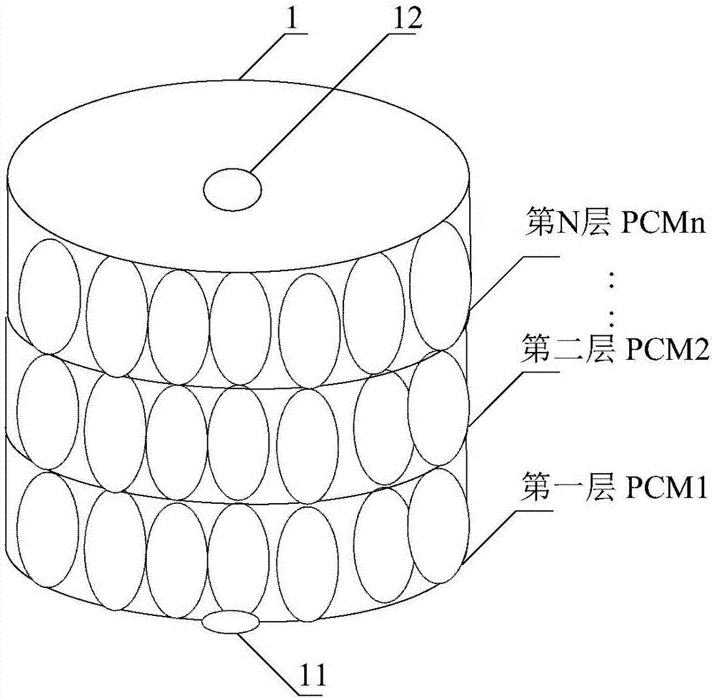
[0069] An embodiment of the present invention provides a heat storage device, including a heat storage tank 1 for heat storage, the heat storage tank 1 is a cylindrical heat storage tank, the diameter and height of the heat storage tank 1 are set It mainly depends on the heat storage temperature and heat storage capacity, and the heat storage tank is a cylinder. A heat input port 11 and a heat output port 12 are respectively arranged on both sides of the heat storage tank body 1. In the heat storage tank body 1, a multi-layer phase change material is arranged in a spirally wound coil tube, and the heat storage tank body in this embodiment The heat tank body 1 can form a channel for the heat transfer medium to circulate between the heat input port 11 and the heat output port 12 by arranging a spirally wound coil tube. The phase change temperature of each layer of phase change material is along the heat input port 11 to the heat output port. 12 directions increase one by one, an...


PUM


Abstract

The invention discloses a heat storage device and system. The heat storage device comprises a heat storage tank for storing heat, a heat inlet and a heat outlet are correspondingly disposed on two sides of the heat storage tank, a plurality of layers of phase change materials are disposed in the heat storage tank, and a flow passage for a heat transfer medium is formed between the heat inlet and the heat outlet through gaps of the multiple layers of the phase change materials; a phase transition temperature of each layer of the phase change materials increases one by one in the direction fromthe heat inlet to the heat outlet, and the phase transition temperature is a melting temperature of which the current temperature of the heat transfer medium reaches a melting point of each layer of the phase change materials. According to the heat storage device and system, the multiple layers of the phase change materials are arranged with different phase transition temperatures, thereby providing enough capacity of stored heat, and accelerating the heat storage efficiency through the latent heat of phase change.

Description

technical field [0001] The invention relates to the technical field of solar heat storage, in particular to a heat storage device and a heat storage system. Background technique [0002] With the shortage of conventional energy and the improvement of people's requirements for environmental quality, the development and utilization of solar energy as a renewable energy has become an important part of the energy strategy of today's society. Due to the discontinuity and instability of solar radiation, the operation of solar power generation systems also has strong fluctuations and intermittences. , Time and space differences, solar heat utilization systems generally have a heat storage system, the heat storage system can convert the solar radiation during the day into heat and store it, and release the heat for use when there is no solar radiation. [0003] In the solar power generation system, in order to provide uninterrupted power to meet the power demand in peak periods and...

Claims


Application Information

Patent Timeline
Patent Type & Authority Applications(China)
IPC IPC(8): F24S60/10F28D20/02
CPCF28D20/021Y02E60/14
Inventor 雷宪章宋鹏翔周育桢谯耕张译文
Owner GLOBAL ENERGY INTERCONNECTION RES INST EURO GMBH
Why Eureka
Try Eureka