An infrared lens precision centering device and centering method based on low stress clamping

A centering device and low-stress technology, which is applied in installation, instrumentation, optics, etc., can solve the problems of easy chipping of the lens, achieve the effect of overcoming the adjustment error and improving the adjustment accuracy

Active Publication Date: 2020-09-11
BEIJING INST OF REMOTE SENSING EQUIP
View PDF3 Cites 0 Cited by
  • Summary
  • Abstract
  • Description
  • Claims
  • Application Information

AI Technical Summary

Problems solved by technology

[0003] The object of the present invention is to provide a precision centering device and centering method for infrared lenses based on low-stress clamping, which solves the problem of being blocked and clamped by the spherical center of the lower surface of the post-installed lens during the process of installing and adjusting the infrared optical system using a dual optical path centering instrument The problem that the process lens is easy to collapse

Method used


Image

  • An infrared lens precision centering device and centering method based on low stress clamping
  • An infrared lens precision centering device and centering method based on low stress clamping

Examples


Embodiment 1

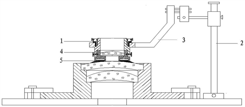
[0028] A precision centering device for infrared lenses based on low-stress clamping includes: a two-dimensional rotation mechanism 1, a three-dimensional translation mechanism 2, a cantilever mechanism 3, and also includes: a positioning conversion lens 4 and a micro-stress clamping positioning device 5.

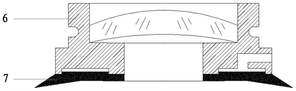
[0029] The micro-stress clamping and positioning device 5 includes a suction cup 7 and a bracket 6, wherein the bracket 6 is a hollow cylindrical structure, and the center hole of the bracket 6 has an annular mounting platform. The suction cup 7 is circular and coaxially bonded to the bottom end of the bracket 6 . Wherein the positioning conversion lens 4 is bonded on the annular mounting platform in the central circular hole of the support 6 .

[0030] The two-dimensional rotating mechanism 1 is a rotating mechanism capable of translation in two directions perpendicular to each other. The three-dimensional translation mechanism is an adjustment mechanism capable of moving...

Embodiment 2

[0034] The specific steps of an infrared lens precision centering method based on low stress clamping are:

[0035] The first step is to calibrate the lens to be installed

[0036] Pre-install the lens to be installed in the lens barrel, observe the spherical center image of the upper and lower surfaces of the lens to be installed on the turntable of the double optical path centering instrument, and adjust the translation and tilt of the centering instrument turntable so that the optical axis of the lens to be installed is coaxial with the rotary axis of the centering instrument turntable .

[0037] The second step is to position the conversion lens 4 and calibrate

[0038] Put the entire precision centering device into the upper optical path of the double optical path centering instrument, use the upper optical path of the centering instrument to observe the upper and lower center images of the positioning conversion lens 4, adjust the optical axis of the positioning convers...


PUM


Abstract

The invention discloses a precision centering device and a centering method for an infrared lens based on low-stress clamping. The device of the invention includes: a two-dimensional rotation mechanism (1), a three-dimensional translation mechanism (2), a cantilever mechanism (3), a positioning The conversion lens (4) and the micro-stress clamping and positioning device (5), wherein the micro-stress clamping and positioning device (5) includes a suction cup (7) and a bracket (6), and the two-dimensional rotating mechanism (1) and the micro-stress clamping and positioning The device (5) is fixed together and located directly above the microstress clamping and positioning device (5), the three-dimensional translation mechanism (2) is fixedly connected with the two-dimensional rotation mechanism (1) through the cantilever mechanism (3), and the positioning conversion lens (4 ) is bonded on the annular mounting platform in the central circular hole of the support (6). The device of the invention solves practical problems such as inaccurate positioning of the post-installed lens and fragile optical material clamping during the process of installing and adjusting the infrared optical system using a double optical path centering instrument, and realizes high-precision and high-efficiency installation and adjustment of the infrared optical system.

Description

technical field [0001] The invention relates to a precision centering device and a centering method for an infrared lens, in particular to a precision centering device and a centering method for an infrared lens based on low-stress clamping. Background technique [0002] The infrared transmission optical system used in the field of aerospace remote sensing has the characteristics of many optical elements, many separation variables, complex structure, and the imaging quality is required to be close to the diffraction limit, which has strict requirements for optical adjustment. The traditional transmission optical system generally adopts the direct mounting and centering method, that is, the eccentricity and inclination of each optical lens are sequentially adjusted to the preset tolerance range on the double optical path centering instrument. However, when this method is installed and adjusted, due to the occlusion of the installed lens, the spherical center image of the lowe...

Claims


Application Information

Patent Timeline
Patent Type & Authority Patents(China)
IPC IPC(8): G02B7/02
CPCG02B7/023
Inventor 白静邓准程军梅那佳曹成真卢治兵
Owner BEIJING INST OF REMOTE SENSING EQUIP
Why Eureka
Try Eureka