
Method for assessing aerodynamic heat of air rudder gaps of aircrafts under unsteady state condition

A technology of air rudders and aircrafts, applied in the direction of instruments, special data processing applications, electrical digital data processing, etc., can solve the problems of large amount of calculation, difficult to grasp aerodynamic thermal evaluation, etc., and achieve the effect of reducing the pressure of design

Active Publication Date: 2018-05-01
BEIJING LINJIN SPACE AIRCRAFT SYST ENG INST +1
View PDF6 Cites 11 Cited by
  • Summary
  • Abstract
  • Description
  • Claims
  • Application Information

AI Technical Summary

Problems solved by technology

[0007] The technical problem to be solved by the present invention is: to overcome the deficiencies of the prior art, aiming at the unsteady flow phenomenon in the gap of the air rudder and the frequent swinging of the air rudder when the two types of unsteady problems lead to the aerodynamic thermal evaluation of the gap area of ​​the air rudder The problem is difficult to grasp and the amount of calculation is huge. The present invention proposes an aerodynamic thermal environment design method for the air rudder gap interference area in an unsteady state, which can effectively consider the aerodynamic thermal change characteristics when there is unsteady flow in the air rudder gap , to establish an aerothermal evaluation method for the air rudder gap under the condition of frequent swinging of the air rudder, which can effectively reduce the redundancy of the evaluation while ensuring the reliability of the evaluation under the condition of acceptable computing resource consumption

Method used


Image

  • Method for assessing aerodynamic heat of air rudder gaps of aircrafts under unsteady state condition
  • Method for assessing aerodynamic heat of air rudder gaps of aircrafts under unsteady state condition
  • Method for assessing aerodynamic heat of air rudder gaps of aircrafts under unsteady state condition

Examples


Embodiment Construction

[0031] Specific embodiments of the present invention will be further described in detail below in conjunction with the accompanying drawings.

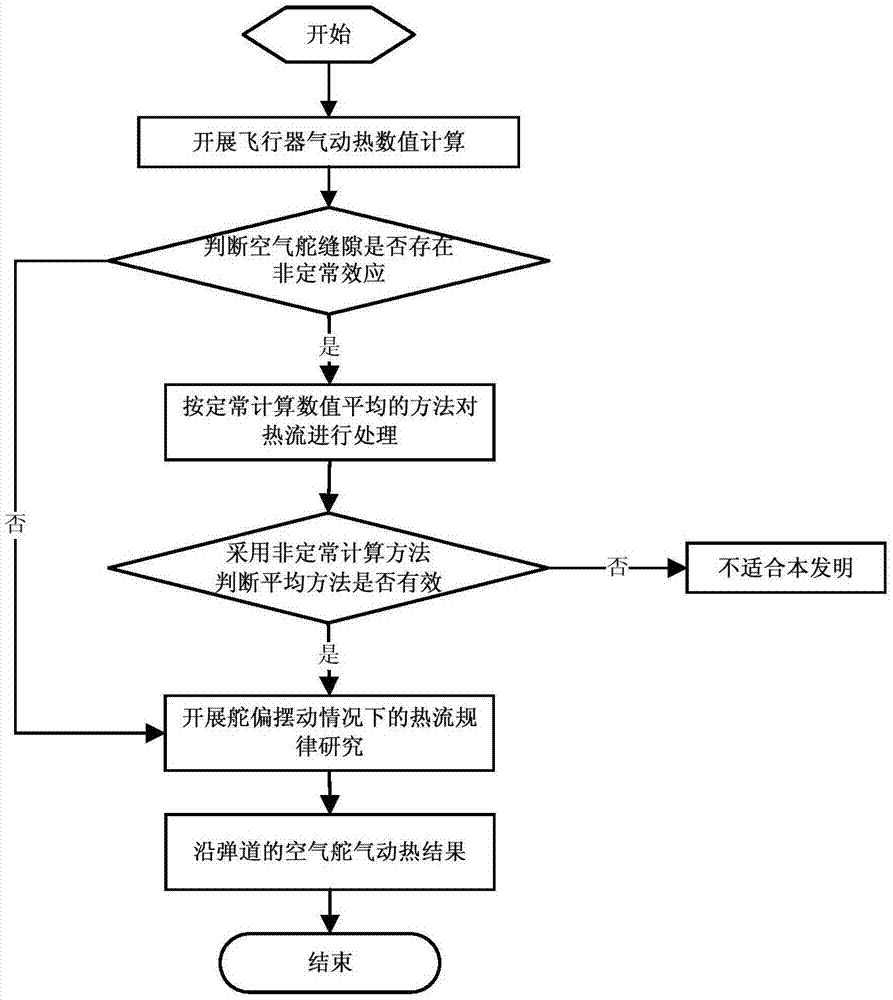
[0032] refer to figure 2 , shows a flow chart of the steps of a thermal environment design method for controlling rudder gaps in an embodiment of the present invention. An aerothermal evaluation method for aircraft air rudder gaps under unsteady conditions, comprising the following steps:

[0033] 1. Numerical calculation of aircraft thermal environment

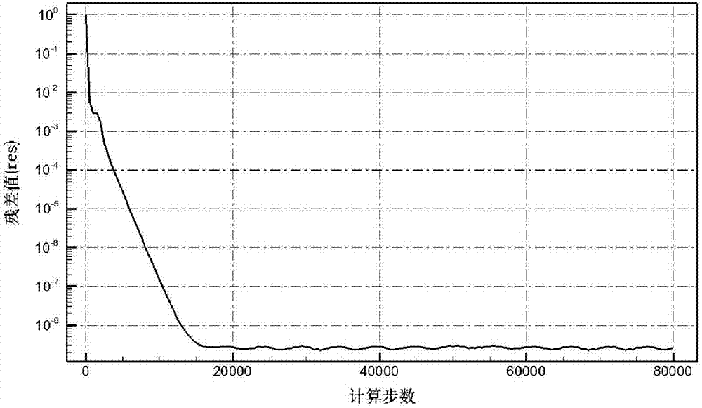
[0034] For the typical flight state of the gliding section, the heat flow on the outer wall surface of the real aircraft is obtained by solving the N-S equation (Equation 1).

[0035]

[0036] In the formula, x, y, z are the coordinates in the Cartesian coordinate system, To solve the vector, is the inviscid flux, is the viscous flux, and t is the physical flow time. Using the finite volume method or finite difference method to numerically discretize the N-S equation, and...


PUM


Abstract

The invention discloses a method for assessing aerodynamic heat of air rudder gaps of aircrafts under unsteady state condition. The method comprises the following steps of: 1, obtaining a heat flow onthe surface of outer wall of an aircraft through numerically solving an N-S equation of an aircraft flow field; 2, judging whether an unsteady effect exists in a rudder gap or not and carrying out corresponding processing; 3, obtaining an average heat flow of a steady method at a feature point in a rudder gap area in a plurality of periods; 4, comparing an average heat flow of unsteady method atthe feature point in the plurality of periods, and carrying out corresponding processing according to conditions; 5, obtaining an interference factor in the rudder gap area, and obtaining a piecewiseanalytic function curve, changing along with rudder deflection, of the interference factor by utilizing a curve fitting method; and 6, embedding the piecewise function curve of the interference factorinto an aerodynamic heat engineering calculation program so as to obtain a rudder gap area heat environment result of the aircraft in a set trajectory time period. The method is capable of effectively decreasing the redundancy of assessment results while ensuring the reliability of air rudder gap aerodynamic heat assessment results.

Description

technical field [0001] The invention relates to an aerothermal evaluation method. Background technique [0002] Good control characteristics and maneuverability are very important to the performance of the aircraft, and the air rudder is an important part of the attitude control and stability of the hypersonic aircraft, which makes the hypersonic aircraft inseparable from the design of the air rudder and the frequent use of the air rudder during flight. swing. Due to the structural characteristics and functional requirements, there will inevitably be gaps between the air rudder and the aircraft cabin, such as figure 1 As shown, the air rudder gap area generally includes the part of the air rudder gap that is in contact with the incoming air and the area near the air rudder that is significantly affected by the flow of the air rudder gap. The air rudder gap is often one of the areas with the most complex flow rules and the most severe aerodynamic heating of the aircraft. ...

Claims


Application Information

Patent Timeline
IPC IPC(8): G06F17/50
CPCG06F30/15G06F30/20G06F2119/08Y02T90/00
Inventor 聂亮李宇聂春生檀妹静王迅曹占伟王振峰周禹闵昌万朱广生
Owner BEIJING LINJIN SPACE AIRCRAFT SYST ENG INST
Features
  • Generate Ideas
  • Intellectual Property
  • Life Sciences
  • Materials
  • Tech Scout
  • Unparalleled Data Quality
  • Higher Quality Content
  • 60% Fewer Hallucinations
Learn More