
Inner flow channel supporting structure of small-medium-sized gas turbine exhaust cylinder

A technology for gas turbines and support structures, applied in mechanical equipment, engine components, machines/engines, etc., can solve problems such as tearing flow channels, high-temperature gas disturbance, excessive stress deformation, etc., to reduce working thermal stress and working temperature , the effect of preventing deformation and tearing

Active Publication Date: 2019-09-24
HANGZHOU TURBINE POWER GRP
View PDF12 Cites 0 Cited by
  • Summary
  • Abstract
  • Description
  • Claims
  • Application Information

AI Technical Summary

Problems solved by technology

[0003] Under the effect of high temperature, due to the large thermal expansion of the inner flow channel as a thin-walled structure, excessive local stress deformation or even tearing of the flow channel will occur when the welded structure is used; if the lap joint structure is used, due to the existence of large gaps , the inner runner cannot be fixed well, and there is disturbance to the flow of high-temperature gas, which affects the vibration and operating efficiency of the whole machine
In the process of gas turbine start-up and shutdown, due to frequent changes in temperature gradient and flow rate, local thermal stress and load cycle changes, the design safety margin of welding and lap joint structures is insufficient, which may easily lead to fatigue damage such as cracks in the local area

Method used


Image

  • Inner flow channel supporting structure of small-medium-sized gas turbine exhaust cylinder
  • Inner flow channel supporting structure of small-medium-sized gas turbine exhaust cylinder
  • Inner flow channel supporting structure of small-medium-sized gas turbine exhaust cylinder

Examples


Embodiment 1

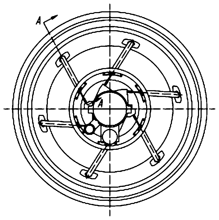
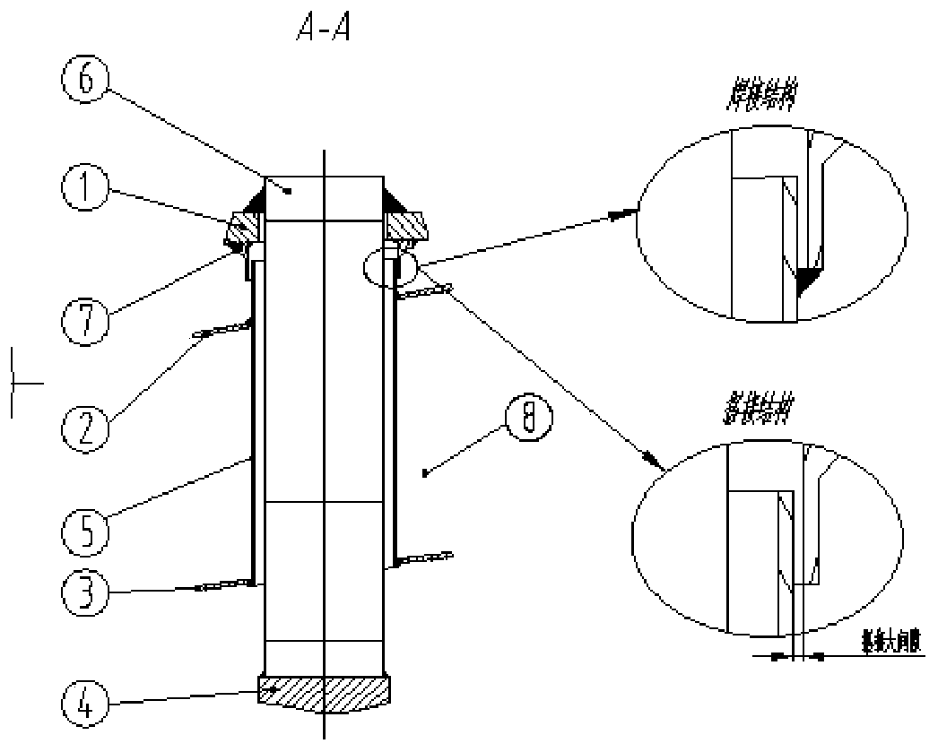
[0034] A small and medium-sized gas turbine exhaust cylinder internal flow channel support structure, including an outer cylinder body 1, a bearing seat 4 and an inner flow channel 8, and also includes a hollow oval tubular support tube 5, integrally formed by two sections of rectangular rods with different widths and the same length Symmetrical support rod 6, and elliptical hollow rounded platform guard plate 7;

[0035] The support rod 6 passes through the inner flow channel 8 and one end with a narrower width is connected to the bearing housing 4, and the other end is connected to the outer cylinder body 1;

[0036] The support tube 5 is sleeved on the outside of the support rod 6;

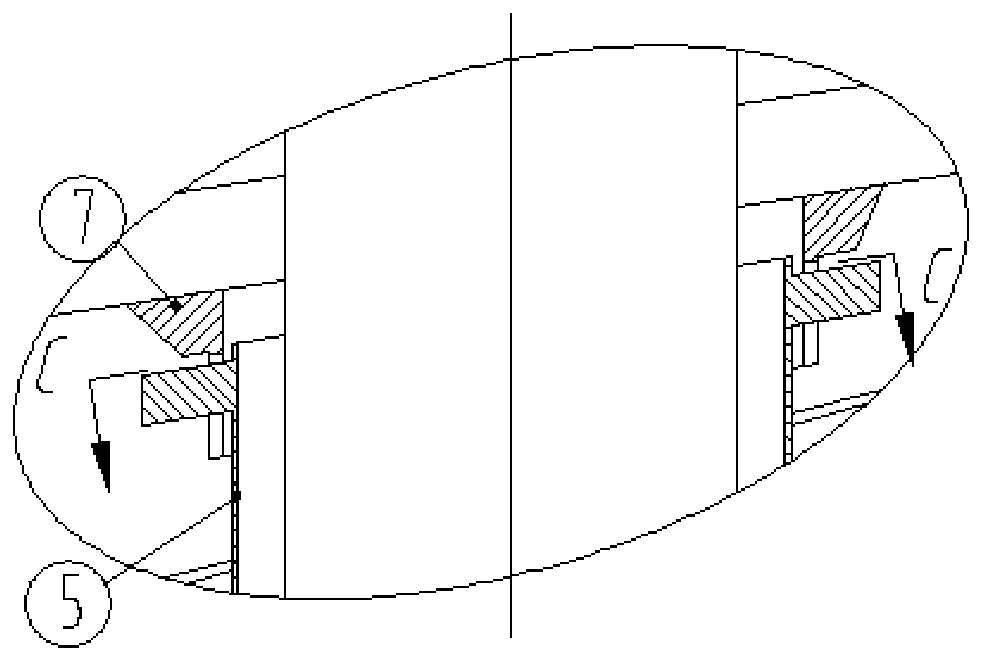
[0037] One end of the guard plate 7 with thicker wall thickness is fixed on the outer cylinder body 1 , and the other end is sleeved on the outside of the support tube 5 , and the support tube 5 can slide inside the guard plate 7 along its axis.

[0038] Two guide blocks 51 are provided on the...

Embodiment 2

[0046] A small and medium-sized gas turbine exhaust cylinder internal flow channel support structure, including an outer cylinder body 1, a bearing seat 4 and an inner flow channel 8, and also includes a hollow oval tubular support tube 5, integrally formed by two sections of rectangular rods with different widths and the same length Symmetrical support rod 6, and elliptical hollow rounded platform guard plate 7;

[0047] The support rod 6 passes through the inner flow channel 8 and one end with a narrower width is connected to the bearing housing 4, and the other end is connected to the outer cylinder body 1;

[0048] The support tube 5 is sleeved on the outside of the support rod 6;

[0049] One end of the guard plate 7 with thicker wall thickness is fixed on the outer cylinder body 1 , and the other end is sleeved on the outside of the support tube 5 , and the support tube 5 can slide inside the guard plate 7 along its axis.

[0050] Two guide blocks 51 are provided on the...

Embodiment 3

[0056] A small and medium-sized gas turbine exhaust cylinder internal flow channel support structure, a small and medium gas turbine exhaust cylinder internal flow channel support structure, including an outer cylinder body 1, a bearing seat 4 and an inner flow channel 8, and also includes a hollow oval tubular support cylinder 5, A symmetrical supporting rod 6 integrally formed by two sections of rectangular rods with different widths and the same length, and an elliptical hollow rounded platform guard plate 7;

[0057] The support rod 6 passes through the inner flow channel 8 and one end with a narrower width is connected to the bearing housing 4, and the other end is connected to the outer cylinder body 1;

[0058] The support tube 5 is sleeved on the outside of the support rod 6;

[0059] One end of the guard plate 7 with thicker wall thickness is fixed on the outer cylinder body 1 , and the other end is sleeved on the outside of the support tube 5 , and the support tube 5...


PUM


Abstract

The invention belongs to the technical field of gas turbine exhaust cylinders, and particularly relates to an inner flow channel supporting structure of a small-medium-sized gas turbine exhaust cylinder. The inner flow channel supporting structure of the small-medium-sized gas turbine exhaust cylinder comprises an outer cylinder body (1), a bearing block (4) and an inner flow channel (8), and is characterized by further comprising a supporting cylinder (5), a symmetrical part supporting rod (6) and an oval hollow inverted circular truncated cone protecting plate (7); the supporting rod (6) penetrates through the inner flow channel (8), one end of the supporting rod (6) is connected with the bearing block (4), and the other end of the supporting rod (6)is connected with the outer cylinder body (1); the supporting cylinder (5) sleeves the outer side of the supporting rod (6), one end of the wall thickness of the protecting plate (7) is fixed on the outer side of the outer cylinder body (1), the other end of the supporting cylinder sleeves the outer side of the supporting cylinder, and the supporting cylinder can slide in the protecting plate along the axis of the supporting cylinder. According to the inner flow channel supporting structure, the working heat stress of the inner flow channel of the exhaust cylinder is reduced, the deformation and tearing of the inner flow channel are prevented, the support stability of the inner flow channel is improved, and the heat stress of the supporting rod is reduced.

Description

technical field [0001] The invention belongs to the technical field of exhaust cylinders of gas turbines, and in particular relates to a support structure for flow passages in exhaust cylinders of small and medium-sized gas turbines. Background technique [0002] A gas turbine is mainly composed of three major components: a compressor, a combustor, and a turbine. The air enters the compressor part from the intake system, and the high-pressure air flowing through the compressor flows into the combustor for full combustion, and then passes through the turbine part to complete energy conversion, and the high-temperature gas flows through the exhaust cylinder part to the subsequent parts (in the process of raising the load of small and medium-sized gas turbines) Gas temperature is in the range of 200°C-600°C). In the current design of gas turbines, the structure of the exhaust cylinder is mainly divided into two categories due to the influence of space: one is that the heavy-du...

Claims


Application Information

Patent Timeline
Patent Type & Authority Applications(China)
IPC IPC(8): F01D25/30
CPCF01D25/30
Inventor 詹长庚郑健生戴斌李祎曼谢健祝华云辛小鹏隋永枫
Owner HANGZHOU TURBINE POWER GRP
Learn More