
A combined burner with adjustable flame distribution

A flame distribution and burner technology, which is applied in the direction of burner, burner, burner cooling, etc., can solve the problem that the burner cannot be reused, and achieve the effect of relieving the easy to be burned by heat, convenient maintenance, and reducing working thermal stress

Active Publication Date: 2021-05-28
CHINA NORTH ENGINE INST TIANJIN
View PDF0 Cites 0 Cited by
  • Summary
  • Abstract
  • Description
  • Claims
  • Application Information

AI Technical Summary

Problems solved by technology

[0004] In view of this, the present invention aims to propose a combined burner with adjustable flame distribution, to solve the problem that the integrated burner cannot be reused, and to improve the adaptability and service life of the combustion plate

Method used


Image

  • A combined burner with adjustable flame distribution
  • A combined burner with adjustable flame distribution
  • A combined burner with adjustable flame distribution

Examples


Embodiment Construction

[0025] It should be noted that, in the case of no conflict, the embodiments of the present invention and the features in the embodiments can be combined with each other.

[0026] In describing the present invention, it should be understood that the terms "center", "longitudinal", "transverse", "upper", "lower", "front", "rear", "left", "right", " The orientations or positional relationships indicated by "vertical", "horizontal", "top", "bottom", "inner" and "outer" are based on the orientations or positional relationships shown in the drawings, and are only for the convenience of describing the present invention and Simplified descriptions, rather than indicating or implying that the device or element referred to must have a particular orientation, be constructed and operate in a particular orientation, and thus should not be construed as limiting the invention. In addition, the terms "first", "second", etc. are used for descriptive purposes only, and should not be understood ...


PUM


Abstract

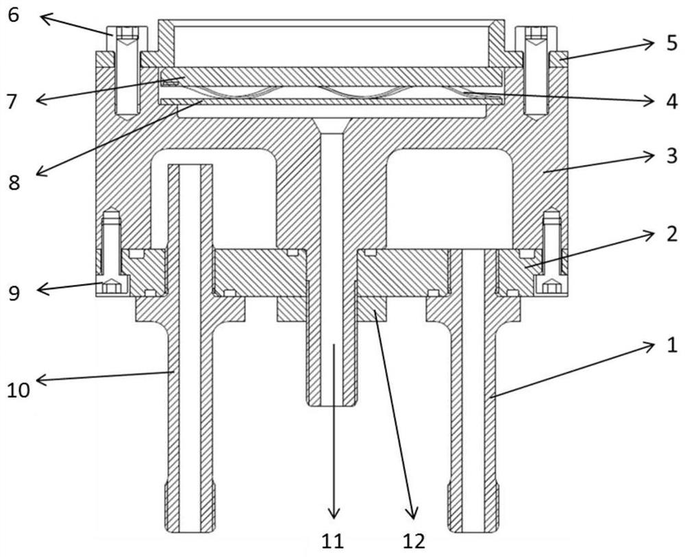
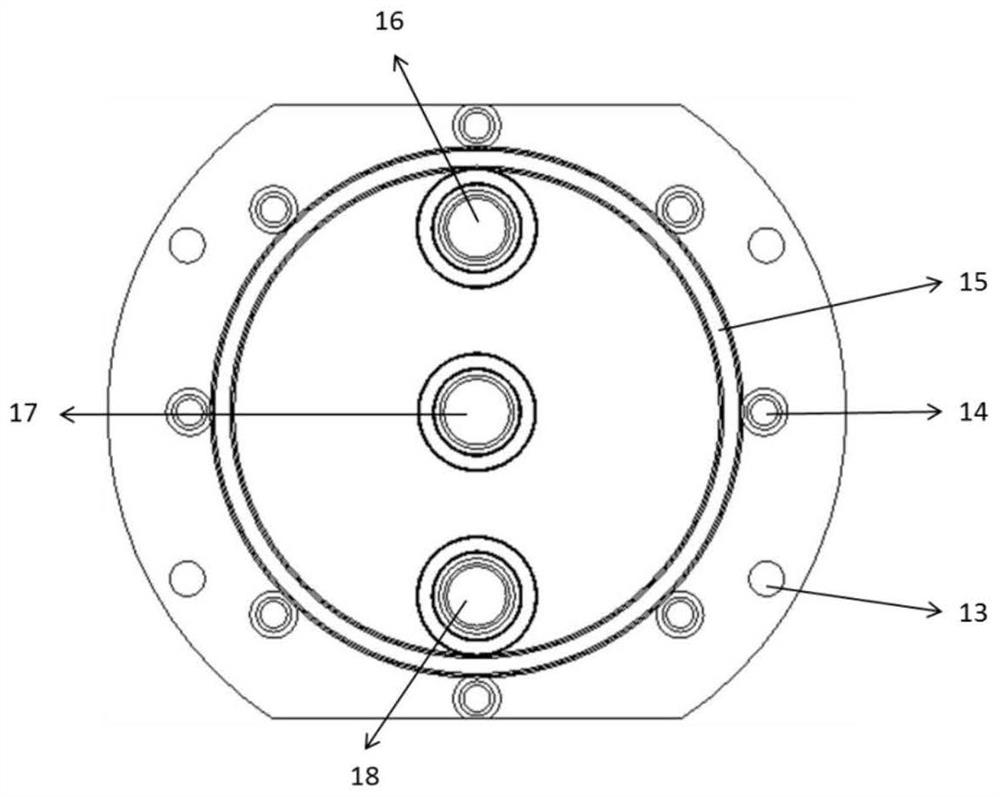
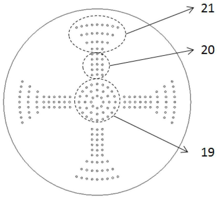
The invention provides a combined burner with adjustable flame distribution, which includes a mounting base plate, a burner body, a gas remixing plate, a wave spring plate, a combustion plate, a flame guide ring, a water inlet pipe and a water outlet pipe. The upper surface is fixedly connected to the burner body; the gas inlet channel formed in the center of the burner body extends downward from the gas inlet pipe installation hole; the water inlet pipe installation hole and the water outlet pipe installation hole are threadedly connected to the water inlet pipe and the water outlet pipe respectively; A gas remixing plate, a wave spring plate, a combustion plate and a flame guide ring are sequentially arranged in the counterbore provided on the top of the burner body from bottom to top. The invention is a combined structure, the main body is connected by thread, not only easy to process and assemble, but also when any part, especially the top combustion plate is damaged, the damaged part can be replaced in time, the maintenance is more convenient, and the cost of use is also reduced. lowered.

Description

technical field [0001] The invention belongs to the technical field of gas heat load test devices, in particular to a combined burner with adjustable flame distribution. Background technique [0002] The gas thermal load test bench can be used for thermal fatigue test and assessment of engine cylinder head, piston and other heated parts. It uses the burner to repeatedly heat the test piece to simulate the thermal shock of the test piece during the working process. Performance and durability are particularly important, and they are the core components of the gas thermal load test bench. [0003] Most of the current burners are integrated and connected by welding or other means. During the heating process, the maximum temperature on the top surface of the burner can reach above 1000°C. During the cooling process or after the burner is stopped, the temperature of the burner will drop. Due to the change in temperature difference, a large thermal stress will be generated, which ...

Claims


Application Information

Patent Timeline
Patent Type & Authority Patents(China)
IPC IPC(8): F23D14/02F23D14/58F23D14/84F23D14/46
CPCF23D14/02F23D14/46F23D14/58F23D14/84F23D2214/00F23D91/00
Inventor 景国玺许春光李鹏马宁王小慧卫军朝文洋张丽强
Owner CHINA NORTH ENGINE INST TIANJIN
Learn More