Embedded fingerprint identification device and method with ultralow stand-by power consumption

A technology for standby power consumption and fingerprint recognition, which is applied in character and pattern recognition, acquisition/organization of fingerprints/palmprints, computer parts, etc. Other operations, user experience discount and other issues, to achieve the effect of good application experience, simple structure, and avoid inconvenience

Pending Publication Date: 2018-05-01
SHENZHEN BETTERLIFE ELECTRONICS SCI & TECH
View PDF4 Cites 6 Cited by
  • Summary
  • Abstract
  • Description
  • Claims
  • Application Information

AI Technical Summary

Problems solved by technology

In this circuit, the battery pack BAT is directly connected to the VDD network of the fingerprint lock module 102 and the controller 101 and cannot be disconnected, otherwise the device cannot work. The fingerprint lock module 102 can control the switch tube M1 through the controller 101 to ensure These high-power consumption devices are powered off when they are not working, and the battery power will not be exhausted in a short time. However, this device still has the defect of high power consumption in embedded applications, because the battery power is low when the system is working normally or in standby mode. All groups need to provide power to the fingerprint lock module 102 and the controller 101
Even if these two modules are in sleep mode, the power consumption in standby is more than 200UA, even 2~6mA. If the finger

Method used


Image

  • Embedded fingerprint identification device and method with ultralow stand-by power consumption
  • Embedded fingerprint identification device and method with ultralow stand-by power consumption
  • Embedded fingerprint identification device and method with ultralow stand-by power consumption

Examples


Embodiment Construction

[0020] The present invention will be described in more detail below in conjunction with the accompanying drawings and embodiments.

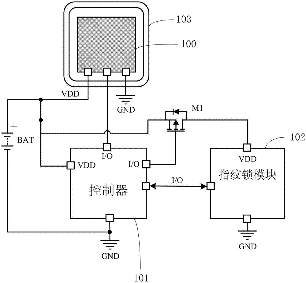
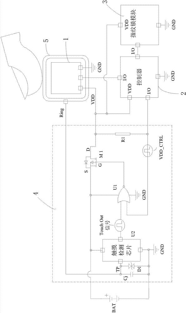
[0021] The invention discloses an embedded fingerprint identification device with ultra-low standby power consumption, please refer to image 3 , which includes a fingerprint sensor 1, a controller 2, a fingerprint lock module 3, a battery BAT and a touch detection unit 4, the fingerprint lock module 3, the controller 2 and the fingerprint sensor 1 are connected in sequence, and the outside of the fingerprint lock module 3 A metal ring 5 is provided, and the touch detection unit 4 includes an input terminal, a detection terminal and an output terminal, the metal ring 5 is connected to the detection terminal of the touch detection unit 4, and the input terminal of the touch detection unit 4 is connected to To the positive pole of the battery BAT, the output end of the touch detection unit 4 is connected to the power end of the fingerprint sensor 1...


PUM


Abstract

The invention discloses an embedded fingerprint identification device with ultralow stand-by power consumption. The embedded fingerprint identification device comprises a fingerprint sensor, a controller, a fingerprint lock module, a battery and a touch detection unit, the fingerprint lock module, the controller and the fingerprint sensor are sequentially connected, the outer side of the fingerprint lock module is provided with a metal ring, the touch detection unit comprises an input terminal, a detection terminal and an output terminal, the metal ring is connected to the detection terminal of the touch detection unit, the input terminal of the touch detection unit is connected to a positive electrode of the battery, the output terminal of the touch detection unit is connected to a powerterminal of the fingerprint sensor, a power terminal of the controller and a power terminal of the fingerprint lock module, the touch detection unit is used for turning on the input terminal and the output terminal when that a finger touches the metal ring is detected, and turning off the input terminal and the output terminal when that a finger touches the metal ring is not detected. According tothe invention, ultralow stand-by power consumption can be achieved, the battery duration can be prolonged, the usage cost can be reduced, the user experience can be improved, and the embedded fingerprint identification device is simple in structure and easy to implement.

Description

technical field [0001] The invention relates to a fingerprint identification device, in particular to an embedded fingerprint identification device and method with ultra-low standby power consumption. Background technique [0002] At present, fingerprint recognition technology has begun to be widely used in various electronic devices, such as smart terminals such as mobile phones and embedded systems, access control security equipment, etc., using the fingerprint characteristics of the human body to identify personal identities. Among all biometric technologies, Fingerprint recognition technology is currently the most mature and widely used biometric technology. The fingerprint sensor 100 includes: an optical fingerprint recognition module, an ultrasonic fingerprint recognition module, a capacitive fingerprint recognition module, etc. The capacitive fingerprint sensor is widely used in fingerprint locks and various smart embedded devices due to its small size. According to ...

Claims


Application Information

Patent Timeline
IPC IPC(8): G06K9/00G07C9/00
CPCG07C9/00563G06V40/1306
Inventor 冯健
Owner SHENZHEN BETTERLIFE ELECTRONICS SCI & TECH
Why Eureka
Try Eureka