Load simulation device for metering equipment

A technology of metering equipment and simulation devices, applied in the direction of measuring devices, measuring electricity, measuring electrical variables, etc., can solve problems such as no phase voltage and phase current, instability, short circuit between phases or phase to ground, etc., to improve work efficiency, The effect of protecting safety

Pending Publication Date: 2018-05-01
何加圣
View PDF6 Cites 3 Cited by
  • Summary
  • Abstract
  • Description
  • Claims
  • Application Information

AI Technical Summary

Problems solved by technology

[0002] Substations are generally composed of switches, high-voltage metering devices, transformers, and low-voltage cabinets. When the substation checks and accepts the metering equipment, the general current, voltage transformers, and energy meters are assembled together after separate verification. At least 7-12, wiring errors often appear phase-to-phase short circuit or phase-to-ground, etc. In addition, there are as many as 28 types of wiring errors caused by secondary leads. In addition, due to unstable personnel in the measurement room or operation by temporary workers, more and more The connection between the multi-watt-hour meter and the transformer is often wrongly connected, such as the wrong phase sequence of the voltage line, the misalignment of the voltage and current line, repeated grounding of the PT, etc. Some units have several wrong connections within a year. A 10kV or 35kV metering box Tens of thousands of losses are caused by wrong wiring, and PT explosions and damages due to wrong wiring are not uncommon. All parties shirk each other's responsibility, often shifting the responsibility to the construction team or equipment manufacturer. Stability and personnel safety also pose a great threat
The reason is that when a new user connects, there is no load on the high-voltage line, and there is no corresponding phase voltage and phase current. Moreover, many current measurement and testing equipment are adjusted from low to high, which cannot reflect the actual situation.

Method used


Image

  • Load simulation device for metering equipment
  • Load simulation device for metering equipment

Examples


Embodiment Construction

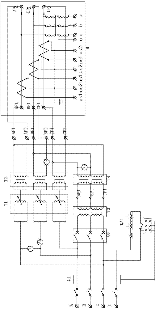
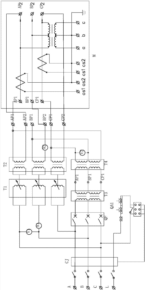
[0014] refer to figure 1 , figure 2 , a metering equipment load simulation device, including a simulation circuit composed of a current simulation branch and a voltage simulation branch in parallel, one end of the simulation circuit is connected to a three-phase four-wire 380V AC input, and the other end receives inspection equipment such as metering Equipment, energy meters and energy meter measurement analyzers, etc. The current emulation branch circuit includes a voltage regulator T1 and a high-voltage current booster T2 connected in sequence, and the voltage regulator T1 is provided with gear selection switches such as 10KV, 20KV, and 35KV. The voltage emulation branch circuit includes a circuit breaker QF, a step-down / regulator T3 and a booster T4 connected in sequence. An AC contactor CJ is connected between the simulation circuit and the 380V AC input.

[0015] In this embodiment, the output voltage of the booster T4 is 10kV, 20kV, 35kV, the output current of the hi...


PUM


Abstract

The invention discloses a load simulation device for metering equipment, which comprises a simulation circuit formed by a current simulation branch and a voltage simulation branch in parallel connection. One end of the simulation circuit is connected with 380 V AC input of a three-phase four-wire system and the other end is connected with to-be-checked equipment. The current simulation branch andthe voltage simulation branch can provide high voltage current, phase voltage and phase current in actual work of the to-be-checked equipment. Before formal electrifying, a simulated load for power grid voltage is used for simulated electrifying outside a power supply system. as the simulation device has a protection function, product damage or explosion does not happen even if wiring of the to-be-checked equipment is wrong, the working efficiency can be improved effectively, the safety of the equipment and the person can be protected better, and the problem that wrong wiring results in explosion and an employee is thus laid-off can be reduced.

Description

technical field [0001] The invention relates to a device for detecting wiring of electric equipment, in particular to a load simulation device for high-voltage electric energy metering equipment. Background technique [0002] Substations are generally composed of switches, high-voltage metering devices, transformers, and low-voltage cabinets. When the substation checks and accepts the metering equipment, the general current, voltage transformers, and energy meters are assembled together after separate verification. At least 7-12, wiring errors often appear phase-to-phase short circuit or phase-to-ground, etc. In addition, there are as many as 28 types of wiring errors caused by secondary leads. In addition, due to unstable personnel in the measurement room or operation by temporary workers, more and more The connection between the multi-watt-hour meter and the transformer is often wrongly connected, such as the wrong phase sequence of the voltage line, the misalignment of th...

Claims


Application Information

Patent Timeline
Patent Type & Authority Applications(China)
IPC IPC(8): G09B23/18G01R31/02
CPCG09B23/187G01R31/50
Inventor 何排枝何加圣马镇锋
Owner 何加圣
Why Eureka
Try Eureka