Electronic component module and manufacturing method thereof

一种电子部件、制造方法的技术,应用在半导体/固态器件制造、电气元件、电固体器件等方向,能够解决屏蔽剥离、反射率降低等问题,达到附着性高、反射率低的效果

Inactive Publication Date: 2018-05-01
TDK CORPARATION
View PDF5 Cites 0 Cited by
  • Summary
  • Abstract
  • Description
  • Claims
  • Application Information

AI Technical Summary

Problems solved by technology

As a method of reducing the reflectance of the metal film, a method of roughening the metal film (blackening treatment) is enumerated. However, when the roughening treatment (blackening treatment) of the metal film is performed, the metal film is etched from the side, and the The shield formed by the metal film may peel off

Method used


Image

  • Electronic component module and manufacturing method thereof
  • Electronic component module and manufacturing method thereof
  • Electronic component module and manufacturing method thereof

Examples


Embodiment 1~5

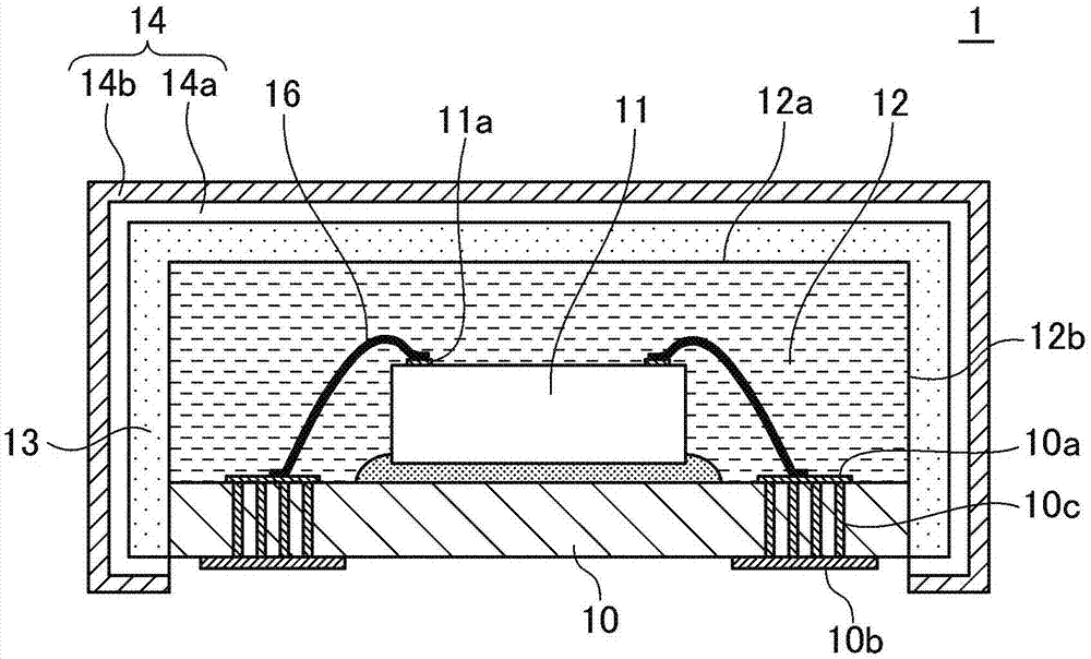
[0047] The actual production has the same figure 1 The samples of Examples 1 to 4 having the same structure as the electronic component module 1 shown have Image 6 A sample of Example 5 having the same structure as the electronic component module 2 shown.

[0048] First, prepare a sample of an electronic component module as an intermediate product in which an electronic component is mounted on a mounting substrate and the electronic component is sealed with a sealing resin (molding resin) containing a filler made of silica (see Figure 4A ). As the mounting board, an FR4 (Flame Retardant Type 4) resin printed circuit board was used.

[0049] Next, a mask tape is pasted on the bottom surface of the mounting substrate to cover the entire bottom surface of the mounting substrate (see Figure 4B ). Next, a conductive film is formed by electroless plating (see Figure 4C ). In the electroless plating process, first, after immersing the electronic component module in an aqueo...


PUM


Abstract

Disclosed herein is an electronic component module that includes, an electronic component, a mold resin that seals the electronic component, a conductive film that covers the mold resin, and a protective film that covers the conductive film. The protective film includes a protective layer and a low reflective layer, and the low reflective layer is free from contacting the conductive film.

Description

technical field [0001] The present invention relates to an electronic component module and a manufacturing method thereof. Background technique [0002] For the purpose of preventing the leakage of electromagnetic wave noise generated from electronic components built in electronic component modules, etc., and preventing the intrusion of electromagnetic wave noise generated from the surrounding environment, an electromagnetic wave shield made of a metal film is used to cover the surroundings of electronic components. Research. In recent years, along with demands for miniaturization and high performance of electronic components, miniaturization and high performance are also required for electromagnetic wave shielding. [0003] A technique for reducing space by directly forming a metal film on the surface of an electronic component module is disclosed. [0004] For example, the electronic component shielding method described in Japanese Patent Application Laid-Open No. 2012-1...

Claims


Application Information

Patent Timeline
Patent Type & Authority Applications(China)
IPC IPC(8): H01L23/552H01L23/29H01L21/56
CPCH01L21/288H01L21/32051H01L21/56H01L21/565H01L23/29H01L23/295H01L23/3121H01L23/552H01L24/32H01L24/48H01L24/73H01L2224/29099H01L2224/32225H01L2224/45099H01L2224/48091H01L2224/48106H01L2224/48227H01L2224/48472H01L2224/73265H01L2924/00H01L2924/00012H01L2924/00014H01L2924/181
Inventor 折笠诚堀川雄平阿部寿之上林义广
Owner TDK CORPARATION
Why Eureka
Try Eureka