
Output overvoltage protection circuit based on floating ground BUCK architecture

A technology for protecting circuits and output overvoltage, applied in electric light sources, electrical components, electroluminescent light sources, etc., can solve the problems of short demagnetization time, failure of output overvoltage protection, easy to trigger overvoltage protection by mistake, etc., to avoid high frequency oscillation, reduce system cost, avoid false triggering and failure effects

Pending Publication Date: 2018-05-01
SHANGHAI ORIENT CHIP TECH CO LTD
View PDF10 Cites 0 Cited by
  • Summary
  • Abstract
  • Description
  • Claims
  • Application Information

AI Technical Summary

Problems solved by technology

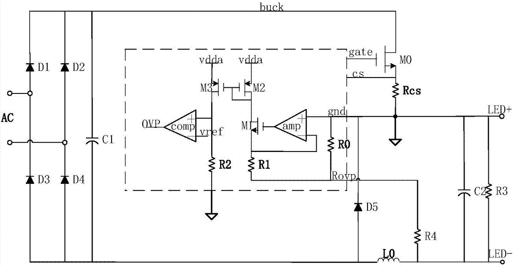
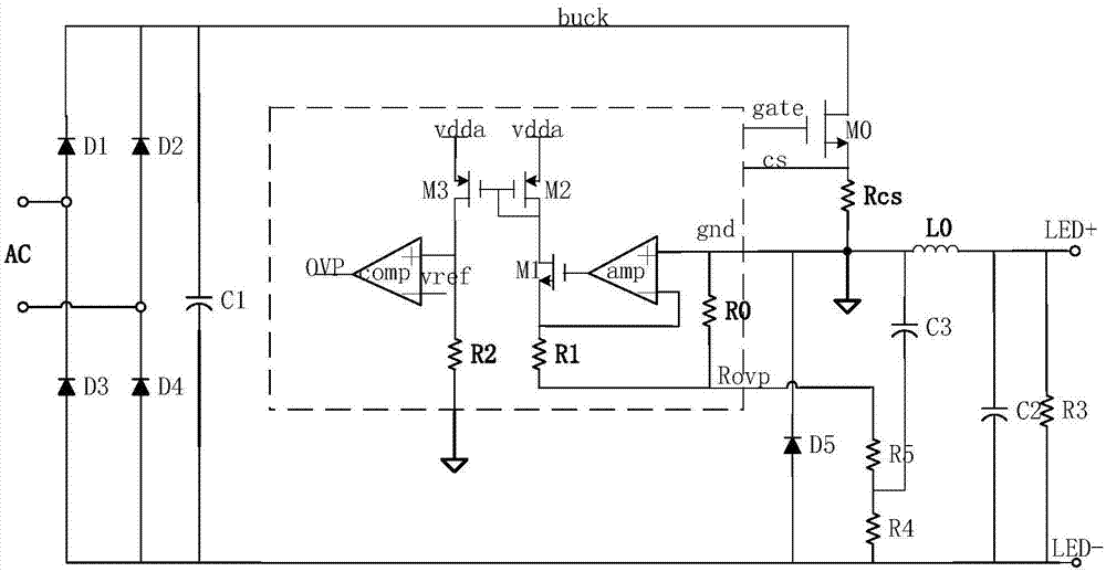
[0004] The above schemes have the following problems: (1) Both schemes do not directly sample the output voltage. When the demagnetization time of the inductor is shorter than the minimum off-time allowed in the chip, the overvoltage protection cannot be triggered, that is, the output overvoltage protection fails; ( 2) The first scheme is easy to accidentally trigger the overvoltage protection when there is noise interference in the resistance voltage division sampling; the second scheme will cause the demagnetization time to be too short when the input voltage is too low and the excitation is not enough to trigger the overvoltage protection by mistake. There is a possibility of false triggering in both solutions, which may easily cause the light to flicker
Although this scheme can avoid figure 1 The problem of high-frequency oscillation interference caused by the connection between the load and the switch node, but it is necessary to increase the resistance and capacitance around the chip, which increases the circuit cost

Method used


Image

  • Output overvoltage protection circuit based on floating ground BUCK architecture
  • Output overvoltage protection circuit based on floating ground BUCK architecture
  • Output overvoltage protection circuit based on floating ground BUCK architecture

Examples


Embodiment Construction

[0042] The above and / or additional aspects and advantages of the present invention will become apparent and readily understood from the following description of embodiments taken in conjunction with the accompanying drawings.

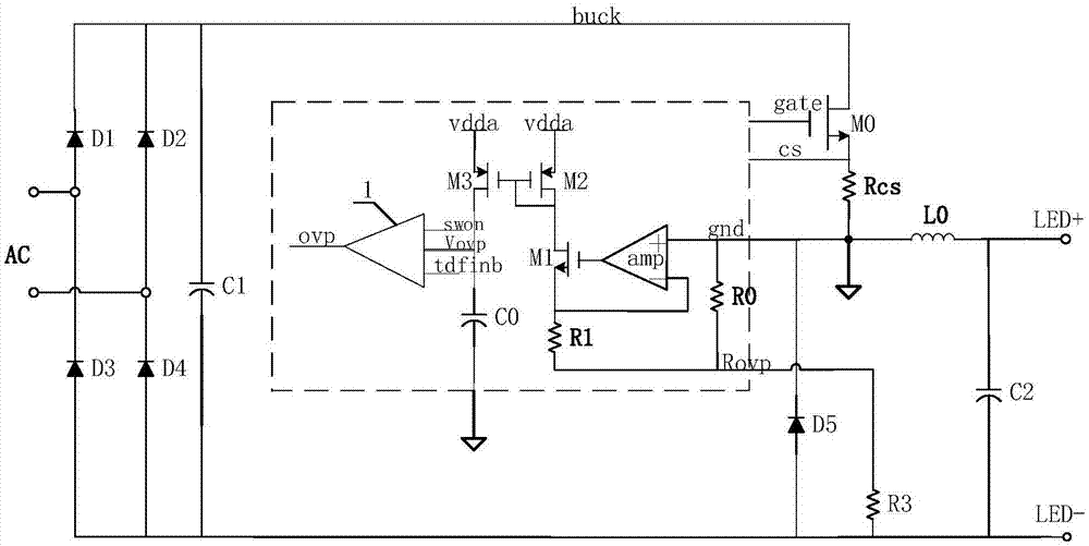
[0043] In order to prevent the output voltage overvoltage of the LED driving circuit, the present invention provides an output overvoltage protection circuit based on a floating BUCK structure. like Figure 4As shown, the overvoltage protection circuit is connected to the LED driving circuit, including an inductor L0, a resistor R3 and a diode D5 arranged outside the LED driving chip (the chip is shown as a dotted frame), and also includes a resistor arranged in the LED driving chip R0, an operational amplifier amp, a MOS transistor M1, a capacitor C0, a resistor R1, a current mirror module composed of MOS transistors M2 and M3, and a voltage detection module 1. Among them, the connection relationship between the components is as follows: one end of th...


PUM


Abstract

The invention provides an output overvoltage protection circuit based on a floating ground BUCK architecture, which comprises an inductor L0, a resistor R3, a diode D5, a resistor R0, an operational amplifier, a MOS tube M1, a resistor R1, a current mirror module and a voltage detection module, wherein one end of the inductor L0 is connected with a positive voltage output end, and the other end ofthe inductor L0 is grounded; one end of the resistor R3 is connected with a negative voltage output end; an anode of the didoe D5 is connected with the negative voltage output end; one end of the resistor R0 is connected with the other end of the L0 and a cathode of the D5, and the other end of the resistor R0 is connected with the other end of the R3; a positive input end of the operational amplifier is connected with one end of the R0; a gate electrode of the MOS tube M1 is connected with an output end of the operational amplifier, and a source electrode of the MOS tube M1 is connected witha negative input end of the operational amplifier; one end of the resistor R1 is connected with the source electrode of the M1, and the other end of the resistor R1 is connected with the other end ofthe R0; an input end of the current mirror module is connected with the drain electrode of the M1, and an output end of the current mirror module is grounded by a capacitor C0; and a first input endof the voltage detection module is connected with the output end of the current mirror module, a second input end of the voltage detection module receives a switching control signal, and a third inputend receives a demagnetization detection signal. According to the invention, false triggering and failure of overvoltage protection can be avoided, and interference to external equipment, which is caused by load high-frequency oscillation, can also be avoided in the premise of not increasing peripheral components.

Description

technical field [0001] The invention relates to the field of LED driving, in particular to an output overvoltage protection circuit based on a floating buck architecture. Background technique [0002] LED driver chips usually need to integrate the output overvoltage protection function to prevent the circuit from being damaged by excessive output voltage under abnormal conditions. When the output terminal of the LED driver circuit is open or abnormally overvoltage, the LED driver chip must trigger the output overvoltage protection function to turn off the output power tube to control the further rise of the output voltage, otherwise the output voltage will continue to rise out of control, which will exceed the device. The ultimate withstand voltage will cause system damage. [0003] With the popularization of LED applications and the reduction of costs, the environment of LED driver applications is becoming more and more complex and harsh. Therefore, in the face of various ...

Claims


Application Information

Patent Timeline
Patent Type & Authority Applications(China)
IPC IPC(8): H05B33/08H05B44/00
CPCH05B45/50H05B45/37Y02B20/30
Inventor 不公告发明人
Owner SHANGHAI ORIENT CHIP TECH CO LTD
Learn More