Sound barrier, catenary and road cut supporting structure into one unit of high-speed railway

A high-speed railway, trinity technology, applied in the direction of roads, buildings, overhead lines, etc., can solve the problem of limited land use scope, and achieve the effect of reducing investment, saving land, and novel structure

Pending Publication Date: 2018-05-04
CHINA RAILWAY ERYUAN ENG GRP CO LTD
View PDF10 Cites 0 Cited by
  • Summary
  • Abstract
  • Description
  • Claims
  • Application Information

AI Technical Summary

Problems solved by technology

[0003] The technical problem to be solved by the present invention is to provide a three-in-one structure of high-speed railway sound barrier, catenary and road cutting support to solve technical problems such as limited land use range, strict noise control, and project investment savings faced by high-speed railways adjacent to urban residential areas

Method used


Image

  • Sound barrier, catenary and road cut supporting structure into one unit of high-speed railway

Examples


Embodiment Construction

[0009] The present invention will be further described below through specific embodiments in conjunction with the accompanying drawings.

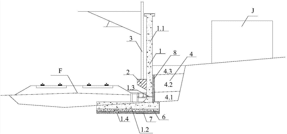
[0010] refer to figure 1 , the trinity structure of the high-speed railway sound barrier, catenary and cutting support of the present invention includes the sound barrier and the catenary support 3 arranged between the high-speed railway cutting F and the residential area J. The sound barrier is a cantilever sound barrier retaining wall 1 with an L-shaped section, which has an upright cantilever 1.1 and a bottom plate 1.2 extending into the high-speed railway cutting F. On the inner side wall of the cantilever 1.1, corbels 2 are arranged at intervals along the line extension direction, and catenary pillars 3 are arranged on the corbels 2 . A backfill layer 4 is provided on the outside of the cantilever sound barrier retaining wall 1 . The cantilever sound barrier retaining wall 1 can be used as the supporting structure of the high-speed r...


PUM


Abstract

The invention discloses a sound barrier, a catenary and a road cut supporting structure into one unit of a high-speed railway, and then the technical problems faced by urban residential areas near thehigh-speed railway such as the limited land area, strict noise control and saving project investment and the like can be solved. A sound barrier arranged between the high-speed railway road cut and the residential area and a catenary pillar are comprised. The sound barrier is a cantilever sound barrier retaining wall with an L-shaped cross-section. And the sound barrier is provided with a vertical cantilever and a bottom plate which extends into the road cut of the high-speed railway. A corbel structure is arranged at intervals at the inner wall of the cantilever along the direction of road extension. The catenary pillar is arranged on the corbel structure. A backfill layer is arranged outside the cantilever sound barrier retaining wall.

Description

technical field [0001] The invention relates to the technical field of high-speed railway embankment, in particular to a three-in-one structure of a sound barrier, a catenary and a cutting retainer. technical background [0002] High-speed railways close to urban residential areas have strict noise control requirements, and face a series of problems such as limited railway land in urban areas and narrow construction space, especially shallow cutting projects. In this regard, if the high-speed railway passes through urban residential areas through bridges or tunnels, the railway line needs to be raised or lowered, which will easily lead to a substantial increase in investment in projects along the line; Structures such as catenary, catenary and roadbed support, etc., if these structures are arranged sequentially in the cross-sectional direction, the land use range of the railway roadbed will be significantly increased. In order to solve the above problems, it is urgent to pr...

Claims


Application Information

Patent Timeline
Patent Type & Authority Applications(China)
IPC IPC(8): E01F8/00E01B2/00B60M1/20
CPCE01B2/00E01F8/0005B60M1/20
Inventor 胡会星赵青海陈伟志曾永红李安洪吴沛沛龚建辉叶世斌李宁唐第甲薛海洋张健
Owner CHINA RAILWAY ERYUAN ENG GRP CO LTD
Why Eureka
Try Eureka