Closed-loop pipe and plate connection assembly
A technology for connecting components and pipe fittings, which is applied in construction, building construction, etc., can solve the problems of narrow internal space of closed-loop pipe fittings and the inability to form connections, etc., and achieve the effect of fast connection
- Summary
- Abstract
- Description
- Claims
- Application Information
AI Technical Summary
Problems solved by technology
Method used
Image

Examples
Embodiment 1
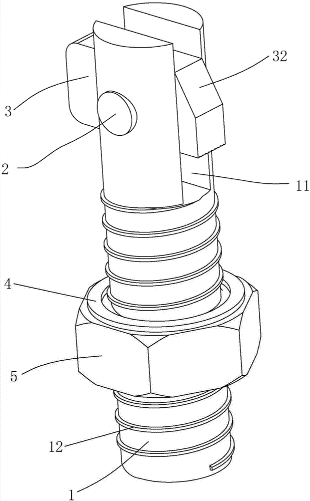
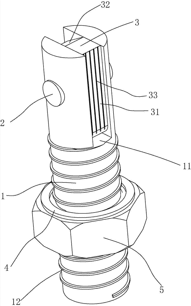
[0037] Embodiment 1: A connection assembly of a closed-loop pipe fitting and a plate, such as Figure 1-2 , including a cylindrical connecting column 1, one end of the connecting column 1 is provided with a rectangular movable groove 11, a rotating shaft 2 is fixed in the movable groove 11, and a rectangular force bearing block 3 is rotated and socketed on the rotating shaft 2. The center of the block 3 deviates from the center of the rotating shaft 2, and because the texture of the stressed block 3 is uniform, its center of gravity and the center are at the same end of the rotating shaft 2; The groove bottom of movable groove 11. The length of the force-bearing block 3 is greater than the diameter of the connecting column 1, so that its two ends extend out of the movable groove 11 after being rotated under force, and can abut against the inner wall of the connecting hole 61 on the closed-loop pipe fitting 6; the height of the force-bearing block 3 is less than that of the con...
Embodiment 2
[0043] Embodiment 2: A connection assembly of a closed-loop pipe fitting and a plate, such as Figure 5 The difference with Embodiment 1 is that a guide part 34 is fixed on the side of the force bearing block 3 close to the cutout 32, the cross section of the guide part 34 is a right triangle, and the slope of the guide part 34 is in the same direction as the slope of the cutout 32.
[0044] Such as Figure 4, a blocking member 13 is fixed on the inner side wall of the movable groove 11 near the bottom of the groove, the blocking member 13 is a cylindrical protrusion, and it resists the side wall adjacent to the force receiving surface 31 in the force receiving block 3; the blocking member 13 is formed by Made of rubber, and bonded to the side wall of the movable groove 11, when the force block 3 abuts on the block 13, the block 13 is compressed, and the force block 3 cannot be deflected under the condition of gravity alone through friction. When the force bearing block 3 and...
Embodiment 3
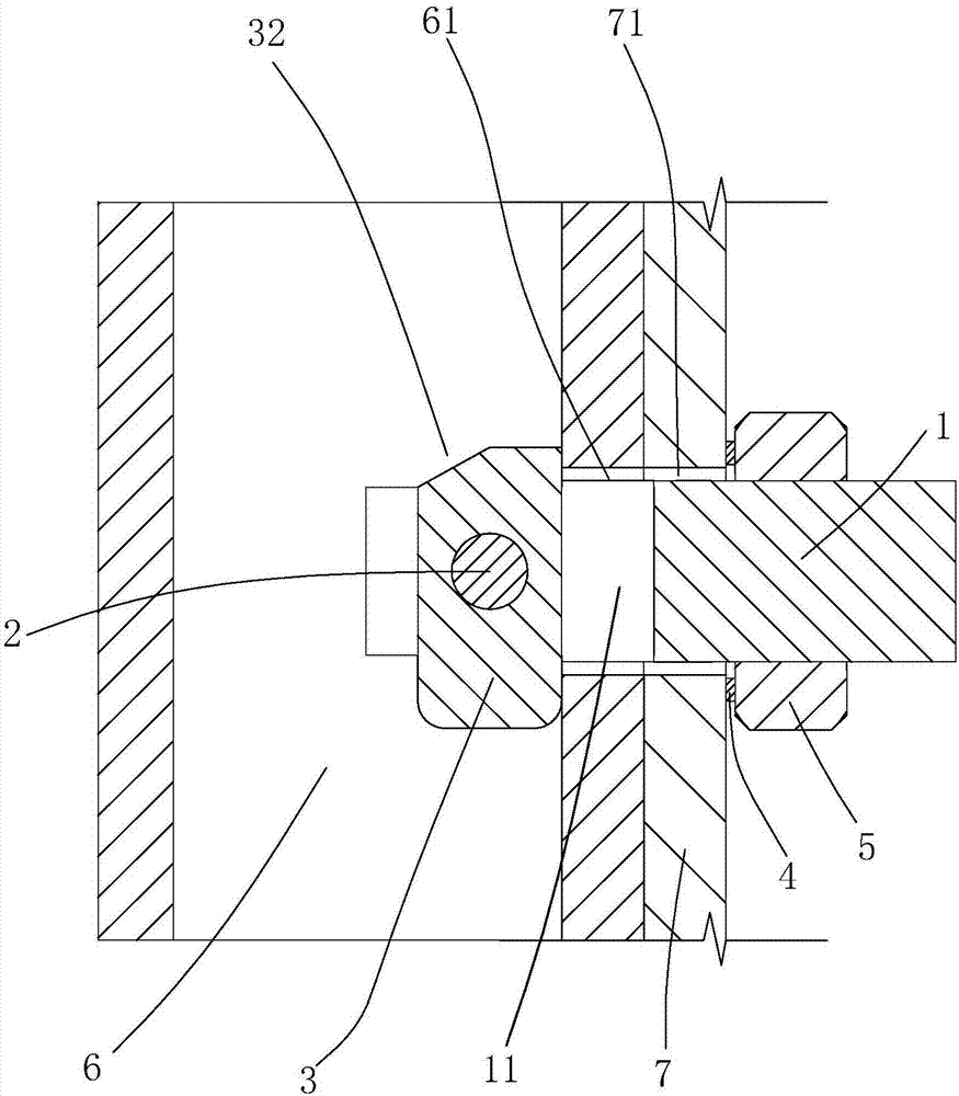
[0049] Embodiment 3: A connection assembly between a closed-loop pipe fitting and a plate, the difference from Embodiment 1 is that: as Figure 7 , a limit column 14 is fixed in the movable groove 11 , and when the force receiving block 3 and the connecting column 1 are on the same straight line, the limit column 14 abuts against the force receiving surface 31 .
[0050] When inserting into the installation hole 71, hold the connecting column 1, the force-bearing surface 31 of the force-bearing block 3 faces downward, and when the force-bearing block 3 extends into the closed-loop pipe fitting 6, turn 180 degrees so that the force-bearing surface 31 of the force-bearing block 3 Upward, at this moment, the force-bearing block 3 rotates eccentrically in the closed-loop pipe 6 due to its own gravity. Pull back the connecting column 1 so that the force bearing surface 31 abuts against the inner wall of the connecting hole 61 of the closed-loop pipe fitting 6, put the elastic washe...
PUM
 Abstract
Description
Claims
Application Information
 - Generate Ideas
- Intellectual Property
- Life Sciences
- Materials
- Tech Scout
- Unparalleled Data Quality
- Higher Quality Content
- 60% Fewer Hallucinations
Browse by: Latest US Patents, China's latest patents, Technical Efficacy Thesaurus, Application Domain, Technology Topic, Popular Technical Reports.
© 2025 PatSnap. All rights reserved.Legal|Privacy policy|Modern Slavery Act Transparency Statement|Sitemap|About US| Contact US: help@patsnap.com