Supercharge Your Innovation With Domain-Expert AI Agents!

Pressure holding tee

A three-way, pass-through technology, applied in the direction of pipeline supports, branch pipelines, mechanical equipment, etc., can solve the problems of high requirements on pipeline surface, inability to realize the connection of two annular pressure test spaces, low operation efficiency, etc. The effect of sealing effect and pressure test efficiency

Active Publication Date: 2020-03-27
CHINA NAT OFFSHORE OIL CORP +1
View PDF7 Cites 0 Cited by
  • Summary
  • Abstract
  • Description
  • Claims
  • Application Information

AI Technical Summary

Problems solved by technology

[0002] The technology of domestic pressure-holding and drilling equipment is not very mature, and the top technology is monopolized by foreign countries. The sealing form of existing products is realized by extrusion and deformation of rubber, which has high requirements on the surface of the pipeline, and cannot realize two ring directions. The connection of the pressure test space, the work efficiency is not high

Method used


Image

  • Pressure holding tee
  • Pressure holding tee
  • Pressure holding tee

Examples


Embodiment Construction

[0021] In order to enable those skilled in the art to better understand the technical solution of the present invention, the present invention will be described in further detail below in conjunction with the accompanying drawings and specific embodiments. And the features in the embodiments can be combined with each other.

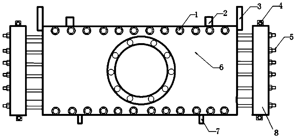
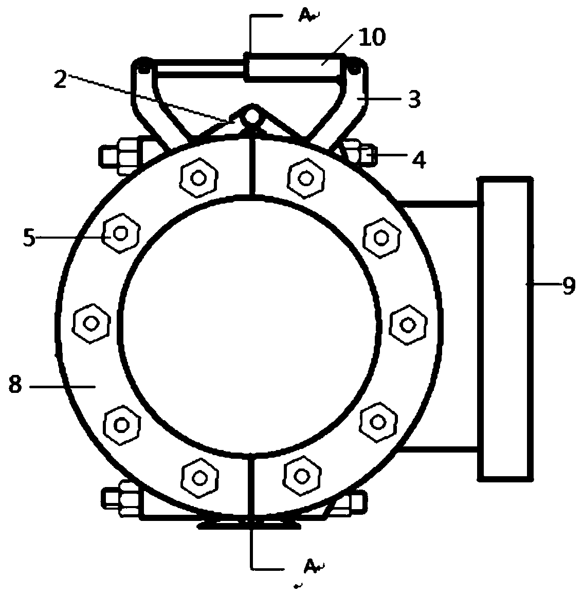
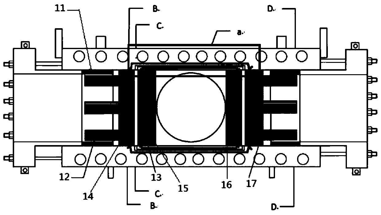
[0022] like Figures 1 to 9 As shown, a pressure-holding tee according to the present invention includes a tee body 6, a hydraulic cylinder 10, and lifting lugs 2. A row of transverse bolts 1 are respectively arranged on the top and bottom of the tee body 6, and the hydraulic cylinder 10 is installed through a hydraulic cylinder mounting column. 3 is connected with the tee body 6, and the hydraulic cylinder 10 can control the opening and closing of the tee body 6. The tee body 6 is provided with a positioning mechanism 28. The positioning mechanism 28 includes a push ring 11, a positioning slip 12 and a shear pin 29. The contact surface between the push ...


PUM


Abstract

The invention discloses a pressure maintaining tee joint. The pressure maintaining tee joint comprises a tee joint body, a hydraulic cylinder and hanging lugs. Each of the upper portion and the lowerportion of the tee joint body is provided with a row of transverse bolts. A hydraulic cylinder is connected with the tee joint body through hydraulic cylinder installing columns. A positioning mechanism is arranged in the tee joint body. Pressing flanges are arranged at the two ends of the tee joint body. Each pressing flange disc is provided with bolt holes and longitudinal bolts. Four limiting rings are sequentially arranged in the tee joint body. The limiting rings and the tee joint body are of an integrated structure. Ring-direction sealing pieces are arranged between the first limiting ring and the second limiting ring and between the third limiting ring and the fourth limiting ring. Ring-direction pressure test spaces are formed between the second limiting ring and the third limitingring. The ring-direction sealing pieces are of a hollow structure and are connected with an injection pipeline. A new sealing form is adopted in the technology, communication of the two ring-direction pressure test spaces is achieved, and the sealing effect and the pressure test efficiency are improved.

Description

technical field [0001] The invention relates to the technical field of pipe fittings, and more particularly to a pressure-holding tee. Background technique [0002] The technology of domestic pressure-holding and drilling equipment is not very mature, and the top technology is monopolized by foreign countries. The sealing form of existing products is realized by extrusion and deformation of rubber, which has high requirements on the surface of the pipeline, and cannot realize two ring directions. The connection of the pressure test space is not efficient. Utility model content [0003] The purpose of the present invention is to avoid the deficiencies in the prior art and provide a pressure-holding tee, the present invention is achieved through the following technical solutions: [0004] A pressure-maintaining tee, including a tee body, a hydraulic cylinder, and lifting lugs. A row of transverse bolts is arranged on the top and bottom of the tee body, and the hydraulic cyl...

Claims


Application Information

Patent Timeline
Patent Type & Authority Patents(China)
IPC IPC(8): F16L41/02F16L3/10
CPCF16L3/1066F16L41/02
Inventor 梁兴华周声结张万兵王和波林华春林先文
Owner CHINA NAT OFFSHORE OIL CORP
Features
  • R&D
  • Intellectual Property
  • Life Sciences
  • Materials
  • Tech Scout
  • Unparalleled Data Quality
  • Higher Quality Content
  • 60% Fewer Hallucinations
Learn More