Propellant combustion smoke concentration testing device

A technology of combustion smoke and testing equipment, which is applied in the direction of measuring equipment, gas turbine engine testing, jet engine testing, etc. It can solve problems such as laborious and laborious, poor response performance, pollution, etc., and achieve safety assurance, easy cleaning and maintenance, The effect of reducing processing difficulty

Inactive Publication Date: 2018-05-04
XIAN MODERN CHEM RES INST
View PDF6 Cites 1 Cited by
  • Summary
  • Abstract
  • Description
  • Claims
  • Application Information

AI Technical Summary

Problems solved by technology

On the one hand, this structure makes the processing of the closed combustion chamber more difficult, especially when the compressive strength of the closed combustion chamber is increased, it imposes strict requirements on the opening design of the combustion chamber and the mechanical properties of optical glass. Optical glass is weak link in its security
When the airtight combustion chamber is working, the interior needs to be filled with high-pressure nitrogen. Once the optical glass is broken, it will cause huge losses to the property and life safety of the device itself and the test laboratory.
On the other hand, it is more difficult to clean and maintain the optical glass in the closed combustion chamber
After the test device is used several times, the inner side of the optical glass on the closed combustion chamber will be polluted by the residue of propellant combustion smoke, which will cause the overall response performance of the device to deteriorate, and the inner side of the optical glass must be cleaned
Dismantling the optical glass for cleaning is not only time-consuming and laborious, but also easily affects the overall airtightness of the closed combustion chamber

Method used


Image

  • Propellant combustion smoke concentration testing device
  • Propellant combustion smoke concentration testing device

Examples


Embodiment Construction

[0027] The present invention will be further explained by the following examples.

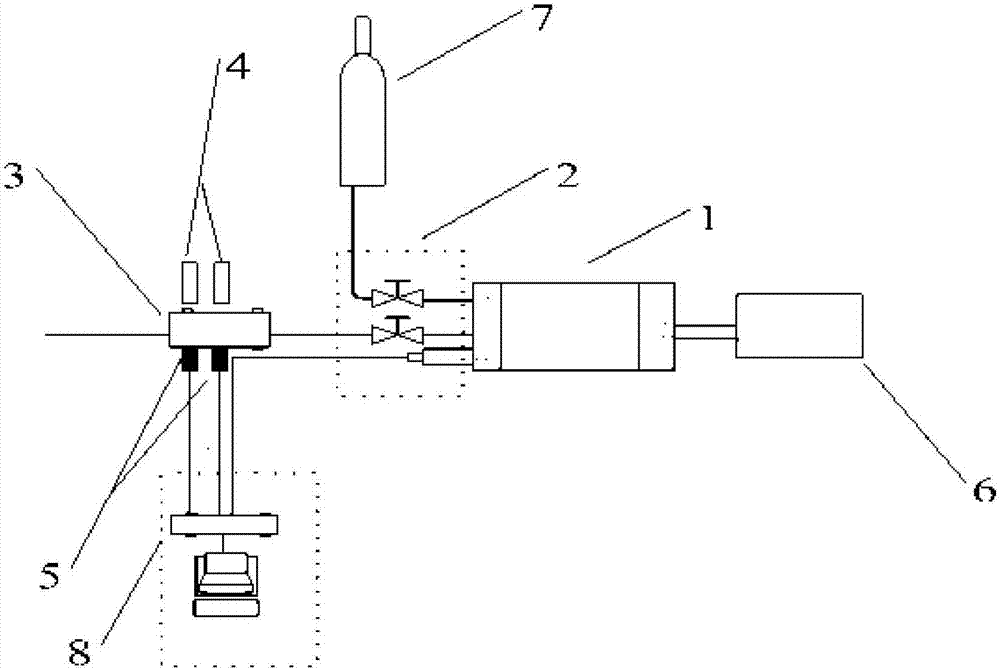
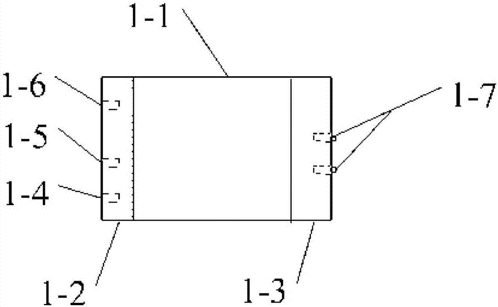
[0028] Such as figure 1 As shown, the propellant combustion smoke concentration test device is composed of a closed combustion chamber 1, a pressure regulation module 2, a test chamber 3, a light source 4, a light intensity detection sensor 5, an ignition power supply 6, a high-pressure gas source 7 and a data acquisition and processing module 8;

[0029] The function of the closed combustion chamber 1 is to provide a combustion environment with a certain initial pressure for the test sample; the function of the module pressure adjustment module 2 is to control the high-pressure gas source 7 to provide the initial pressure for the closed combustion chamber 1, and to control the closed combustion chamber 1 and the test chamber. 3 on and off; the light source 4 and the light intensity detection sensor 5 are respectively located on both sides of the glass window of the test chamber 3; the ignition...


PUM


Abstract

The invention discloses a propellant combustion smoke concentration testing device. The device is mainly composed of a closed combustion chamber, a pressure adjusting module, a test chamber, light sources, light intensity detection sensors, an ignition power source, a high-pressure gas source and a data acquisition and processing module. The pressure adjusting module adjusts the pressure in the closed combustion chamber and controls connection and disconnection of the closed combustion chamber and the test chamber. Symmetrical detection windows are arranged on the test cavity, and the light sources and the light intensity detection sensors are arranged on the two sides of the detection windows of the test cavity respectively; light intensity change when smoke passes through the test cavity is detected. Compared with a traditional smoke concentration testing device, the combustion chamber is separated from the test cavity, so that on the one hand, the structure of the closed combustionchamber is simple, and the difficulty of design and processing of the device is reduced; on the other hand, the requirement on the pressure resistance strength of the test cavity is low by dynamically testing smoke, and meanwhile, the test cavity is easy to clean and maintain. The device can be used for testing the combustion smoke concentration of propellants in a small dosage.

Description

technical field [0001] The invention relates to a propellant combustion smoke concentration testing device, in particular to a combustion smoke concentration testing device for propellant small-dose test samples. Background technique [0002] The solid propellant and its cladding materials produce a lot of smoke when the rocket engine is working, which will directly affect the guidance and stealth performance of the missile. Solid propellant smoke concentration is an important indicator that must be strictly controlled during the development and production of low characteristic signal propellants. Establishing a measurement and evaluation method for propellant smoke concentration is an important content in propellant formulation research and weapon model index requirements . [0003] In the field of propellant engine plume smoke testing, there is 801.1 "Solid Propellant Exhaust Plume Infrared Transmittance Test Smoke Channel Method" in the national military standard GJB 770...

Claims


Application Information

Patent Timeline
Patent Type & Authority Applications(China)
IPC IPC(8): G01M15/14G01N21/17
CPCG01M15/14G01N21/17
Inventor 王长健仪建华许毅赵凤起孙美轩春雷孙志华秦钊梁勇
Owner XIAN MODERN CHEM RES INST
Why Eureka
Try Eureka