Mechanical laser radar and counterweight method for same
A laser radar and mechanical technology, applied in the field of mechanical laser radar and its counterweight, can solve the problems of error, waste of time and materials, waste of manpower and material resources, reduction of dynamic balance performance, etc., to ensure high precision and improve service life , The effect of reducing requirements and the consumption of man-hours
- Summary
- Abstract
- Description
- Claims
- Application Information
AI Technical Summary
Problems solved by technology
Method used
Image
Examples
Embodiment 1
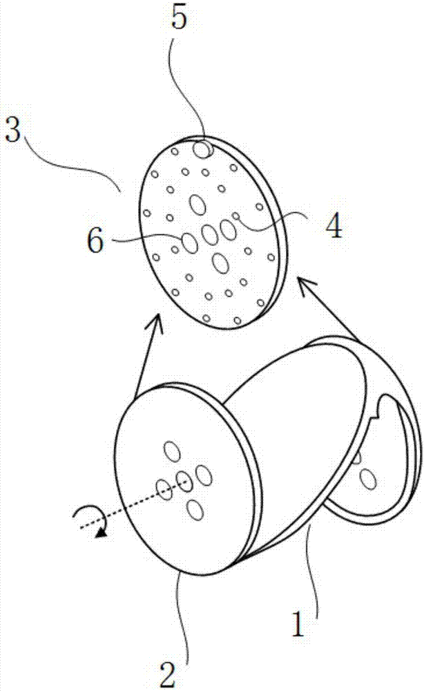
[0041] figure 1 A preferred embodiment of a mechanical lidar according to the invention is shown. The mechanical lidar includes a laser emitting module, a scanning control module, a laser receiving module and a timing processing module, wherein the scanning control module includes a rotating load 1 for connecting with the motor shaft of the mechanical lidar, so as to rotate together with the motor shaft , the rotating load 1 includes 1 reflective mirror surface and 2 counterweight surfaces 2, of which 1 reflective mirror surface and 2 counterweight surfaces 2 are in "N" shape, the reflective mirror surface is elliptical, and is 45° to the motor axis. A reflector is installed on the mirror surface; the counterweight surface 2 is circular, and the motor shaft passes through the counterweight surface 2 and is perpendicular to the counterweight surface 2 . The scanning control module also includes a counterweight panel 3 for adjusting the dynamic balance of the scanning control m...
Embodiment 2
[0057] This embodiment is basically the same as Embodiment 1. For the sake of brevity, in the description process of this embodiment, the same technical features as Embodiment 1 will not be described, and only the differences between this embodiment and Embodiment 1 will be described:
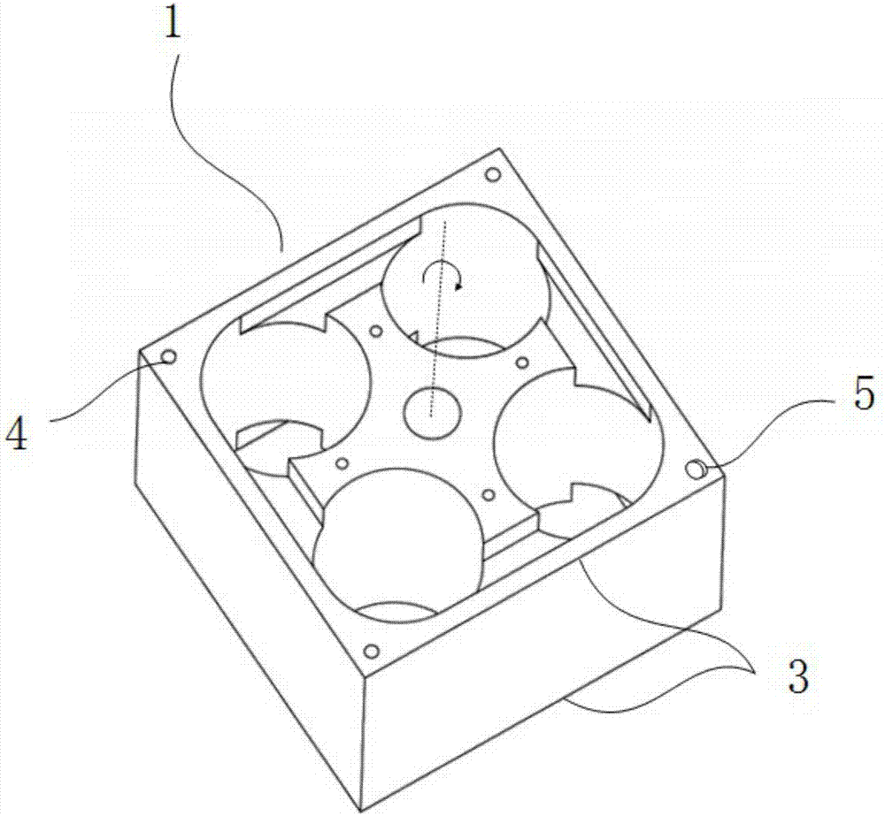
[0058] Such as figure 2 As shown, in this embodiment, the rotating load 1 is a cuboid structure with a square bottom, which includes 4 mirror surfaces and 2 counterweight surfaces 2, wherein the 4 mirror surfaces are respectively 4 sides of the cuboid, and the motor The axis of the shaft is collinear with the central axis of the cuboid structure; the two counterweight surfaces 2 respectively adopt the top surface and the bottom surface of the cuboid structure. Four counterpoints 4 are respectively arranged on the two counterweight surfaces 2 (in this embodiment, all counterpoints 4 are counterweight holes 41), and these four counterpoints 4 are distributed at four vertices of the counterweight...
Embodiment 3
[0062] This embodiment is basically the same as Embodiment 1. For the sake of brevity, in the description process of this embodiment, the same technical features as Embodiment 1 will not be described, and only the differences between this embodiment and Embodiment 1 will be described:
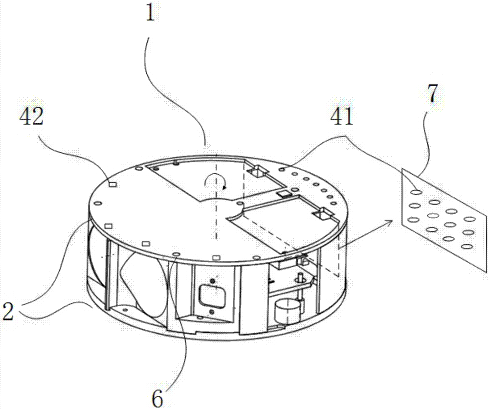
[0063] Such as image 3 As shown, in this embodiment, the rotating load 1 is a cylindrical structure with a circular bottom surface, which includes a mirror surface and two counterweight surfaces 2, wherein the mirror surface is located inside the cylindrical structure; the two counterweights Surface 2 is the top surface and the bottom surface of the cylindrical structure respectively, and the axis of the motor shaft is collinear with the axis of the cylindrical structure. The counterweight panels 3 for adjusting the dynamic balance of the scanning control module are arranged on the two counterweight surfaces 2, and 11 counterpoints 4 are arranged on each counterweight panel 3, preferably the r...
PUM
 Abstract
Description
Claims
Application Information
 - R&D
- Intellectual Property
- Life Sciences
- Materials
- Tech Scout
- Unparalleled Data Quality
- Higher Quality Content
- 60% Fewer Hallucinations
Browse by: Latest US Patents, China's latest patents, Technical Efficacy Thesaurus, Application Domain, Technology Topic, Popular Technical Reports.
© 2025 PatSnap. All rights reserved.Legal|Privacy policy|Modern Slavery Act Transparency Statement|Sitemap|About US| Contact US: help@patsnap.com


