
A kind of mechanical laser radar and its counterweight method

A lidar and mechanical technology, applied in instruments, measuring devices, and re-radiation, etc., can solve the problems of error, time and material waste, reduce dynamic balance performance, manpower and material waste, etc., to ensure high precision and improve use. The effect of longevity, reduction in requirements and consumption of labor hours

Active Publication Date: 2020-01-07
WUHAN WANJI INFORMATION TECH
View PDF7 Cites 1 Cited by
  • Summary
  • Abstract
  • Description
  • Claims
  • Application Information

AI Technical Summary

Problems solved by technology

[0003] In the prior art, most of the standard screws are manually cut off on site, screwed into the counterweight hole of the rotating load, and fixed with fixing glue. On the one hand, in the process of cutting the standard screws, the weight is completely dependent on manual Experience and feeling, there are large errors and waste of time and materials. On the other hand, because the fixing glue also has a certain weight, adding the fixing glue will affect the adjusted dynamic balance and reduce the dynamic balance performance. If it is reworked, then It is necessary to add cumbersome procedures such as removing the fixing glue, which will inevitably cause greater waste of manpower and material resources

Method used


Image

  • A kind of mechanical laser radar and its counterweight method
  • A kind of mechanical laser radar and its counterweight method
  • A kind of mechanical laser radar and its counterweight method

Examples


Embodiment 1

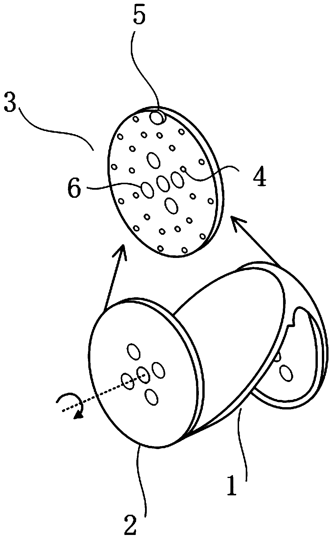
[0041] figure 1 A preferred embodiment of a mechanical lidar according to the invention is shown. The mechanical lidar includes a laser emitting module, a scanning control module, a laser receiving module and a timing processing module, wherein the scanning control module includes a rotating load 1 for connecting with the motor shaft of the mechanical lidar, so as to rotate together with the motor shaft , the rotating load 1 includes 1 reflective mirror surface and 2 counterweight surfaces 2, of which 1 reflective mirror surface and 2 counterweight surfaces 2 are in "N" shape, the reflective mirror surface is elliptical, and is 45° to the motor axis. A reflector is installed on the mirror surface; the counterweight surface 2 is circular, and the motor shaft passes through the counterweight surface 2 and is perpendicular to the counterweight surface 2 . The scanning control module also includes a counterweight panel 3 for adjusting the dynamic balance of the scanning control m...

Embodiment 2

[0057] This embodiment is basically the same as Embodiment 1. For the sake of brevity, in the description process of this embodiment, the same technical features as Embodiment 1 will not be described, and only the differences between this embodiment and Embodiment 1 will be described:

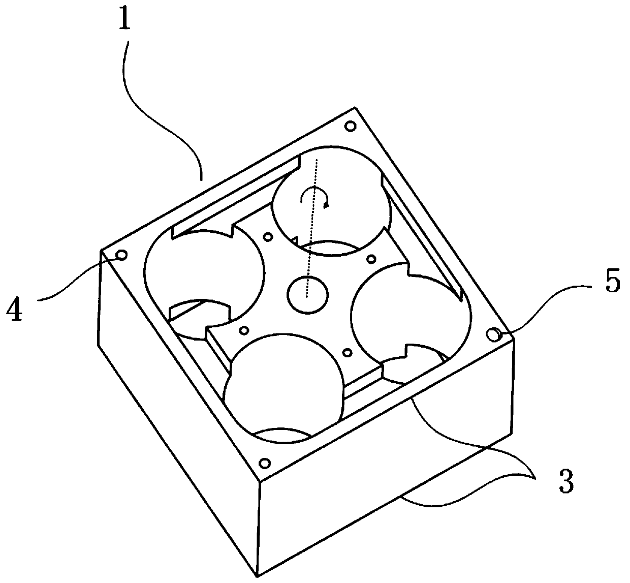
[0058] Such as figure 2 As shown, in this embodiment, the rotating load 1 is a cuboid structure with a square bottom, which includes 4 mirror surfaces and 2 counterweight surfaces 2, wherein the 4 mirror surfaces are respectively 4 sides of the cuboid, and the motor The axis of the shaft is collinear with the central axis of the cuboid structure; the two counterweight surfaces 2 respectively adopt the top surface and the bottom surface of the cuboid structure. Four counterpoints 4 are respectively arranged on the two counterweight surfaces 2 (in this embodiment, all counterpoints 4 are counterweight holes 41), and these four counterpoints 4 are distributed at four vertices of the counterweight...

Embodiment 3

[0062] This embodiment is basically the same as Embodiment 1. For the sake of brevity, in the description process of this embodiment, the same technical features as Embodiment 1 will not be described, and only the differences between this embodiment and Embodiment 1 will be described:

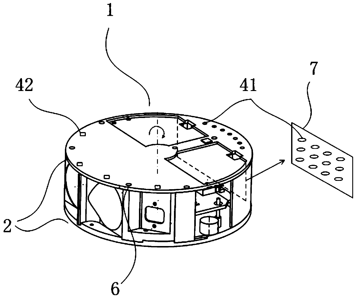
[0063] Such as image 3 As shown, in this embodiment, the rotating load 1 is a cylindrical structure with a circular bottom surface, which includes a mirror surface and two counterweight surfaces 2, wherein the mirror surface is located inside the cylindrical structure; the two counterweights Surface 2 is the top surface and the bottom surface of the cylindrical structure respectively, and the axis of the motor shaft is collinear with the axis of the cylindrical structure. The counterweight panels 3 for adjusting the dynamic balance of the scanning control module are arranged on the two counterweight surfaces 2, and 11 counterpoints 4 are arranged on each counterweight panel 3, preferably the r...


PUM


Abstract

The invention relates to the technical field of laser radar, and discloses a mechanical laser radar and its counterweight method, which includes: a rotating load used to connect with the motor shaft of the mechanical laser radar, and the rotating load includes a reflective mirror surface and a counterweight surface, The axis of the motor shaft passes through the counterweight surface; the counterweight panel used to adjust the dynamic balance of the scanning control module, the counterweight panel is connected with or formed by the counterweight surface of the rotating load, and the counterweight panel is set There are a plurality of counterpoints for welding counterweights, and the plurality of counterweights are spaced around a circle centered on the axis of the motor shaft. The mechanical laser radar and its counterweight method provided by the present invention can dynamically weld the unfixed counterweight weight to the place to be counterweighted, while ensuring high precision, reduce the requirement for manual experience and the consumption of labor hours; avoid the traditional The problems introduced by the process of adding fixing glue in the counterweight fixing method.

Description

technical field [0001] The invention relates to the technical field of laser radar, in particular to a mechanical laser radar and a counterweight method thereof. Background technique [0002] In the mechanical laser radar, there are inevitably mechanical rotating parts, so that the single laser beam scans a surface, and the accuracy of its mechanical rotation directly affects the measurement accuracy and related performance of the mechanical laser radar. The key factor of service life, therefore, in the production process of mechanical laser radar, accurately adjusting the dynamic balance of rotating parts is the top priority of producing high-performance, long-life mechanical laser radar, and improving the efficiency of dynamic balance adjustment is An important part of increasing productivity. [0003] In the prior art, most of the standard screws are manually cut off on site, screwed into the counterweight hole of the rotating load, and fixed with fixing glue. On the one...

Claims


Application Information

Patent Timeline
Patent Type & Authority Patents(China)
IPC IPC(8): G01S7/481G01S17/02
CPCG01S7/4817G01S17/02
Inventor 汪俊徐威胡攀攀
Owner WUHAN WANJI INFORMATION TECH
Learn More