Eureka AIR delivers breakthrough ideas for toughest innovation challenges, trusted by R&D personnel around the world.

Method for calibrating parabolic catadioptric camera using spatial straight lines

A camera and catadioptric technology, applied in the field of computer vision, can solve the problems of the limited range of cameras and the inability of effective information to meet people's needs, and achieve simple results.

Inactive Publication Date: 2018-05-04
YUNNAN UNIV
View PDF4 Cites 3 Cited by
  • Summary
  • Abstract
  • Description
  • Claims
  • Application Information

AI Technical Summary

Problems solved by technology

[0003] The shooting range of traditional cameras is very limited, and the effective information obtained cannot meet people's needs, so there is the birth of panoramic cameras, among which panoramic cameras can be divided into central and non-central

Method used


Image

  • Method for calibrating parabolic catadioptric camera using spatial straight lines
  • Method for calibrating parabolic catadioptric camera using spatial straight lines
  • Method for calibrating parabolic catadioptric camera using spatial straight lines

Examples


Embodiment

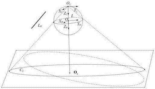
[0055] The invention proposes a method for linearly solving the internal parameters of a parabolic catadioptric camera by using three straight lines in space as targets. The experimental template structural schematic diagram that the present invention adopts is as figure 1 shown. The implementation of the present invention will be described in more detail with an example below.

[0056] The template used to calibrate the parabolic catadioptric camera is a unit viewing sphere model in space and three non-parallel straight lines in space, such as figure 1 shown. Utilize the method among the present invention to carry out calibration for the parabolic catadioptric camera that is used for experiment, concrete steps are as follows:

[0057] 1. Fit the equation of the image of three straight lines in the image

[0058] The image size used in the present invention is 600×800. Use a parabolic catadioptric camera to take an experimental image containing three non-parallel straight...


PUM


Abstract

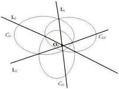
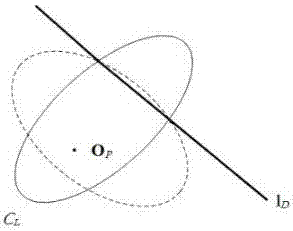
The invention relates to a method for calibrating a parabolic catadioptric camera using spatial straight lines. The camera is calibrated using three straight lines in space as targets. First, in a unit virtual globe model, three non-parallel lines in space are projected and are projected onto an image plane to form three intersecting quadratic curves, and because the two quadratic curves intersectat two real intersecting points, the two intersecting points form a straight line. However, due to the presence of noise, the three straight lines do not intersect at one point but form a triangle. The center of gravity of the triangle can be considered as the approximate principal point on the image plane. Secondly, epipolar lines of the principal point about the three quadratic curves are solved respectively; as can be learnt from the relationship between the epipolar lines of poles, the epipolar line of the principal point with respect to the quadratic curve is a vanishing line, and each vanishing line and the corresponding quadratic curve are intersected at an image of two ring points, and thus intrinsic parameters of the camera are solved.

Description

technical field [0001] The invention belongs to the field of computer vision and relates to a method for solving internal parameters of a parabolic catadioptric camera by using three straight lines in space. Background technique [0002] The purpose of computer vision research is to allow computers to recognize the three-dimensional real environment from two-dimensional images. Computers can not only perceive the structure and motion information of three-dimensional objects, including its shape, position, posture, motion, etc., but also recognize and understand them. . In fact, most of Marr's computational theoretical framework and other computational theoretical frameworks formed in the 1980s involve using geometric methods to calculate the shape, position, attitude, and motion of three-dimensional objects in the environment. Existing camera calibration methods can be divided into traditional camera calibration methods and camera self-calibration methods. The traditional ...

Claims


Application Information

Patent Timeline
Patent Type & Authority Applications(China)
IPC IPC(8): G06T7/80G06T3/00G06T11/20
CPCG06T7/80G06T11/203G06T2207/20068G06T3/08
Inventor 赵越浦绍芬
Owner YUNNAN UNIV
Why Eureka
Eureka Blog
Learn More