
Control method and control circuit of three-phase four-wire system static VAR generator

A three-phase four-wire system, static var technology, applied in circuit devices, AC network circuits, reactive power adjustment/elimination/compensation, etc., can solve the problems of poor compensation accuracy, increased output current distortion rate, power grid harmonics pollution and other issues

Pending Publication Date: 2018-05-04
深圳市海思瑞科电气技术有限公司
View PDF0 Cites 0 Cited by
  • Summary
  • Abstract
  • Description
  • Claims
  • Application Information

AI Technical Summary

Problems solved by technology

The traditional solution is generally to configure passive compensation equipment, such as: capacitance compensation device, to compensate the distribution network, but such devices have problems such as slow response speed, poor compensation accuracy, and easy resonance with the system
[0004] However, due to the adjustment effect of the three-phase switch of the static var generator of the three-phase four-wire system, it is easy to cause zero-sequence harmonic components in the neutral line, such as the 3rd harmonic and the 9th harmonic, etc., making the three-phase four-wire system The output current distortion rate of the static var generator increases, causing additional harmonic pollution to the power grid, and even causing the device to fail to operate stably in severe cases

Method used


Image

  • Control method and control circuit of three-phase four-wire system static VAR generator
  • Control method and control circuit of three-phase four-wire system static VAR generator
  • Control method and control circuit of three-phase four-wire system static VAR generator

Examples


Embodiment Construction

[0075] It should be understood that the specific embodiments described here are only used to explain the present invention, not to limit the present invention.

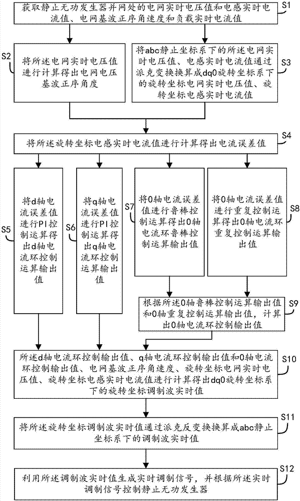
[0076] refer to figure 1 , propose a control method for a three-phase four-wire static var generator of the present invention, comprising the following steps,

[0077] S1, obtain the grid real-time voltage value and inductor real-time current value, grid voltage fundamental wave positive sequence angular velocity and load real-time current value at the grid-connected point of static var generator;

[0078] S2, calculating the real-time voltage value of the power grid to obtain the positive sequence angle of the fundamental voltage of the power grid;

[0079] S3, convert the real-time voltage value of the power grid and the real-time current value of the inductor under the abc static coordinate system into the real-time voltage value of the rotating coordinate power grid and the real-time current value of the inductan...


PUM


Abstract

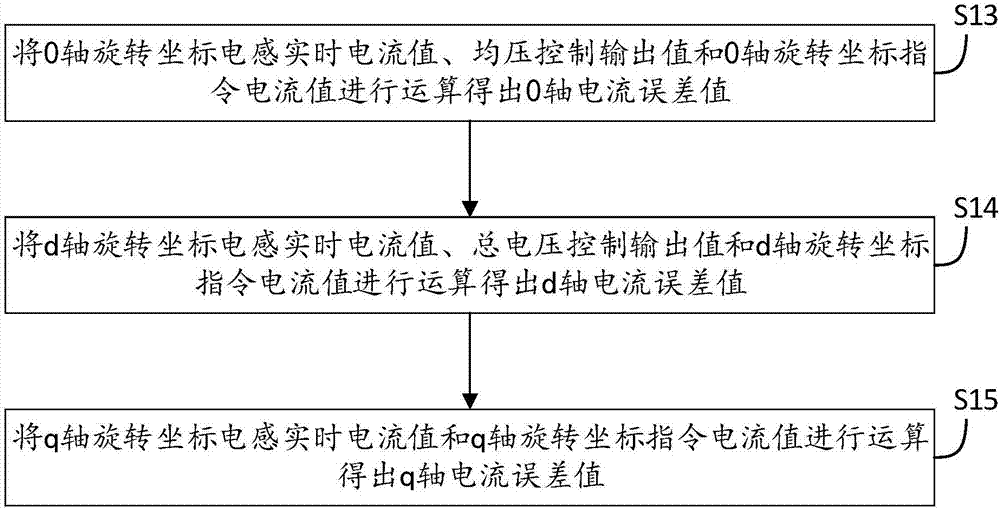
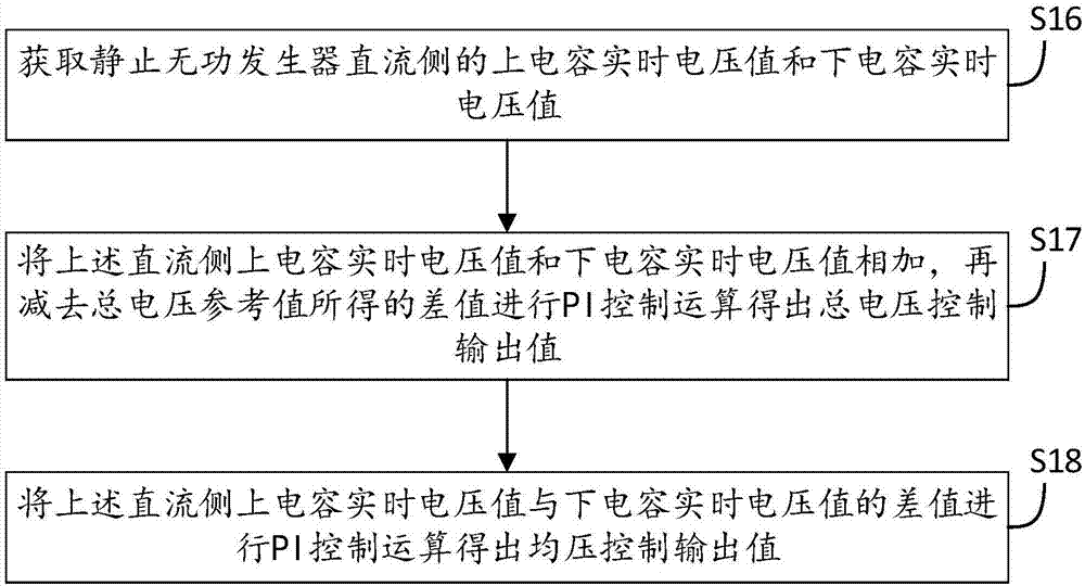
The invention discloses a control method and a control circuit of a three-phase four-wire system static VAR generator. The control method includes respectively subjecting 0-axis rotational coordinateinductance real-time current value and 0-axis current directive value to robust control algorithm and repetitive control algorithm to obtain 0-axis current loop control output value; subjecting d-axiscurrent loop and q-axis current loop to PI control algorithm respectively to obtain d-axis current loop control output value and q-axis current loop control output value; calculating to obtain rotational coordinate modulation wave real-time value according to the d-axis current loop output value, the q-axis current loop control output value, the 0-axis current loop control output value, power grid voltage fundamental wave positive sequence angular velocity, rotational coordinate power grid real-time voltage value and the rotational coordinate inductance real-time current value, generating a real-time modulation signal by means of reverse-Park transform algorithm according to the rotational coordinate modulation wave real-time value and the power grid voltage fundamental wave positive sequence angular velocity, and according to the real-time modulation signal, effectively suppressing neutral conductor current harmonics injected into the power grid from the three-phase four-wire systemstatic VAR generator.

Description

technical field [0001] The invention relates to the technical field of reactive power compensation for distribution networks, in particular to a control method and a control circuit for a three-phase four-wire static var generator. Background technique [0002] The three-phase four-wire static var generator is an active power electronic device. The three-phase four-wire static var generator is used to compensate the reactive power of the distribution network, which can realize real-time fast and stepless compensation compensation. At the same time, it has the advantages of improving power factor and maintaining grid voltage stability. And with the advancement of technology and the reduction of the cost of core components, in my country's three-phase four-wire power supply system, the three-phase four-wire static var generator has a tendency to gradually replace the traditional capacitor compensation device. [0003] In the civil three-phase four-wire power supply mode, ther...

Claims


Application Information

Patent Timeline
IPC IPC(8): H02J3/18
CPCH02J3/1842H02J2203/20Y02E40/10
Inventor 阮阳李志超洪波
Owner 深圳市海思瑞科电气技术有限公司
Learn More