Eureka AIR delivers breakthrough ideas for toughest innovation challenges, trusted by R&D personnel around the world.

Method and device for controlling energy storage system

A technology of an energy storage system and a control method, which is applied in the field of electronic power conversion technology and control, can solve the problems of off-grid power failure, micro-grid collapse, inability to guarantee uninterrupted power supply, etc., and achieves the effect of expanding application fields and enhancing auxiliary functions.

Inactive Publication Date: 2018-05-04
GUANGZHOU ZHIGUANG ELECTRIC CO LTD +1
View PDF5 Cites 7 Cited by
  • Summary
  • Abstract
  • Description
  • Claims
  • Application Information

AI Technical Summary

Problems solved by technology

The traditional control strategy is active power and reactive power (PQ) control when connected to the grid, and adjusted to voltage frequency (Vf) control when it is off-grid. It is when the grid is connected to the grid and switched off the grid, resulting in the failure of the mode switching and the shutdown and restart, which cannot guarantee the uninterrupted power supply
In the microgrid, the energy storage system acts as the main power supply. Once it runs off-grid, other power sources in the entire microgrid need the voltage frequency output by the energy storage system as a reference. Other power sources in the grid will go off the grid and lose power, and the entire microgrid will collapse
Therefore, energy storage systems urgently need the ability to seamlessly switch between on-grid and off-grid modes, but it is difficult for existing technical solutions to achieve this

Method used


Image

  • Method and device for controlling energy storage system
  • Method and device for controlling energy storage system
  • Method and device for controlling energy storage system

Examples


Embodiment Construction

[0053] Hereinafter, exemplary embodiments of the present disclosure will be described in more detail with reference to the accompanying drawings. Although exemplary embodiments of the present disclosure are shown in the drawings, it should be understood that the present disclosure can be implemented in various forms and should not be limited by the embodiments set forth herein. On the contrary, these embodiments are provided to enable a more thorough understanding of the present disclosure and to fully convey the scope of the present disclosure to those skilled in the art.

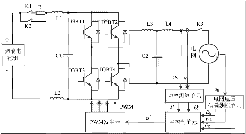
[0054] figure 1 A schematic diagram of an energy storage system architecture according to an embodiment of the present invention is shown. Among them, the energy storage battery pack is the energy storage device in the present invention, which can be lithium ion batteries, lead-acid batteries, lead-carbon batteries, sodium-sulfur batteries, vanadium flow batteries and other electrochemical secondary batteries...


PUM


Abstract

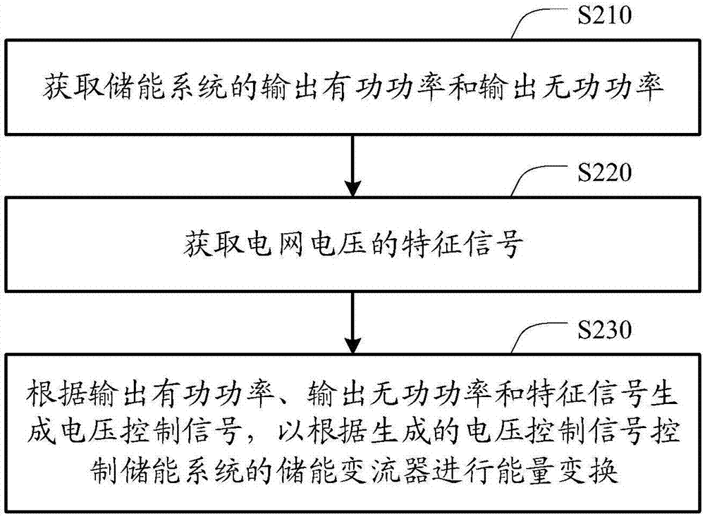
The invention discloses a method and device for controlling an energy storage system. The method includes the steps of obtaining output active power and output reactive power of the energy storage system; acquiring a characteristic signal of a grid voltage; and generating a voltage control signal according to the output active power, the output reactive power and the characteristic signal, so as to control an energy storage converter of the energy storage system according to the generated voltage control signal to perform energy conversion. According to the technical scheme, control signal generation methods for the energy storage system in an off-grid mode and a grid-connected mode are not distinguished, the strategy conversion between PQ control and Vf control during traditional off-gridand grid-connected switching is avoided, seamless switching of off-grid and grid-connected working modes is achieved, the application field of the energy storage system is greatly expanded, auxiliaryfunctions of the energy storage system are enhanced, and the method and device for controlling the energy storage system are suitable for the development needs of smart grids and microgrids.

Description

Technical field [0001] The invention relates to the field of electronic power conversion technology and control, in particular to a control method and device of an energy storage system. Background technique [0002] Energy storage systems often work in grid-connected mode and off-grid mode, involving the switching of the two modes. When working in grid-connected mode, the energy storage system acts as a current source, but once the grid fails or the power is out of maintenance , The energy storage system needs to be able to quickly and seamlessly switch to the off-grid working mode to ensure uninterrupted power supply for important loads. The traditional control strategy is active and reactive power (PQ) control when grid-connected, and voltage frequency (Vf) control when off-grid. Due to the different control modes, over-voltage or over-current often occurs when switching between grid-connected and off-grid, especially When the grid is connected and disconnected from the grid,...

Claims


Application Information

Patent Timeline
IPC IPC(8): H02J3/38H02J3/44H02J3/32H02J9/06
CPCH02J3/32H02J3/38H02J3/388H02J3/44H02J9/061H02J2203/20
Inventor 吴志鹏许贤昶吴胜兵石磊李继华
Owner GUANGZHOU ZHIGUANG ELECTRIC CO LTD
Why Eureka
Eureka Blog
Learn More