Torque Alignment Nut And Installation Tool

A nut and tool technology, applied in the field of fluid flow control equipment, can solve problems such as easy deformation or rounding of nuts and tools, large operator cost and investment, and reduced efficiency, so as to improve operator efficiency, reduce operating costs, and facilitate Removed effects

Pending Publication Date: 2018-05-08
FISHER CONTROLS INT LLC
View PDF6 Cites 0 Cited by
  • Summary
  • Abstract
  • Description
  • Claims
  • Application Information

AI Technical Summary

Problems solved by technology

For example, the edges of nuts and tools may be easily deformed or rounded if the parts are not aligned precisely
With parts not properly aligned, the tool may slip and cause damage
In addition, multiple people are often required to maintain proper alignment in order to ensure that parts can be used multiple times, resulting in reduced efficiency and greater operator cost and investment

Method used


Image

  • Torque Alignment Nut And Installation Tool
  • Torque Alignment Nut And Installation Tool
  • Torque Alignment Nut And Installation Tool

Examples


Embodiment Construction

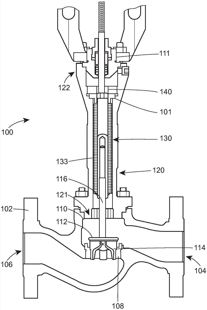
[0017] In general, the present disclosure relates to fluid flow control devices 100 (eg, valves or regulators) for regulating fluid flow. like figure 1 As shown, apparatus 100 includes a valve body 102 defining an inlet 104 , an outlet 106 , a throat 108 disposed between inlet 104 and outlet 106 , and a bonnet opening 110 . Apparatus 100 also includes a control element 112 disposed within throat 108 of valve body 102 , and apparatus 100 includes a valve plug 114 and an elongated stem 116 coupled to valve plug 114 . The apparatus 100 also includes an extension bonnet 120 , a bellows 130 disposed in the extension bonnet 120 , and a bellows nut 140 . System 100 may include any number of additional components and / or subsystems (such as, for example, including a valve coupled to valve body 102 at throat 108 ) as known to those skilled in the art and will not be described herein for the sake of brevity. seat trim assembly, any number of gaskets, bushings, etc.). An example of dev...


PUM


Abstract

A fluid flow control device includes a valve body defining an inlet, an outlet, a throat disposed between the inlet and the outlet, and a bonnet opening, a control element having a valve plug and an elongated stem coupled to the valve plug, an extension bonnet coupled to the bonnet opening, a bellows disposed in the extension bonnet, and a bellows nut threaded onto the stem to secure the bellows in the extension bonnet and form a seal around the stem. The bellows nut includes a first surface, a second surface, a throughbore extending between the first surface and a second surface receiving thestem, and a tapered channel extending from the first surface toward the second surface. The tapered channel comprises a first width formed by the first surface and a second width that is greater thanthe first width for receiving a tool and facilitating placement.

Description

technical field [0001] The present disclosure relates generally to a fluid flow control device, and more particularly to a system for installing and removing a bellows nut from a fluid flow control device. Background technique [0002] In many types of fluid flow control devices and assemblies, extension members are used to position sensitive mechanisms at a safe distance from potentially hazardous environments. For example, a regulator and / or valve may use an extended bonnet to move an actuator component (eg, an actuator housing) a safe distance from extreme temperatures that can often exceed 450 degrees Fahrenheit. These extended bonnets may typically include sealing mechanisms such as bellows to provide enhanced sealing around the valve stem and other components. [0003] Bellows nuts are commonly used to secure the bellows in the extended bonnet. Generally, considerable torque (eg, about 250 pounds per foot (lb.-ft.) or greater) is required to secure the bellows nut to...

Claims


Application Information

Patent Timeline
Patent Type & Authority Applications(China)
IPC IPC(8): B25B27/14F16K1/32F16K41/10
CPCB25B27/14F16K1/32F16K41/10B25B27/24F16K31/46F16K1/54F16K1/12F16K27/02
Inventor C·A·麦库恩
Owner FISHER CONTROLS INT LLC
Why Eureka
Try Eureka