Cargo grabbing device for industrial robot

An industrial robot and grabbing device technology, which is applied in the field of cargo grabbing devices, can solve the problems of easy falling of goods and unstable grabbing of goods, and achieve the effects of improved safety performance, good stability and high work efficiency

Inactive Publication Date: 2018-05-08
GUANGXI RUIKE IND ROBOT CO LTD
View PDF5 Cites 10 Cited by
  • Summary
  • Abstract
  • Description
  • Claims
  • Application Information

AI Technical Summary

Problems solved by technology

[0004] The purpose of the present invention is to solve the problem that the industrial robot grasps the goods unstable and the goods are easy to fall in the prior art, and proposes a goods grasping device for industrial robots

Method used


Image

  • Cargo grabbing device for industrial robot
  • Cargo grabbing device for industrial robot
  • Cargo grabbing device for industrial robot

Examples


Embodiment 1

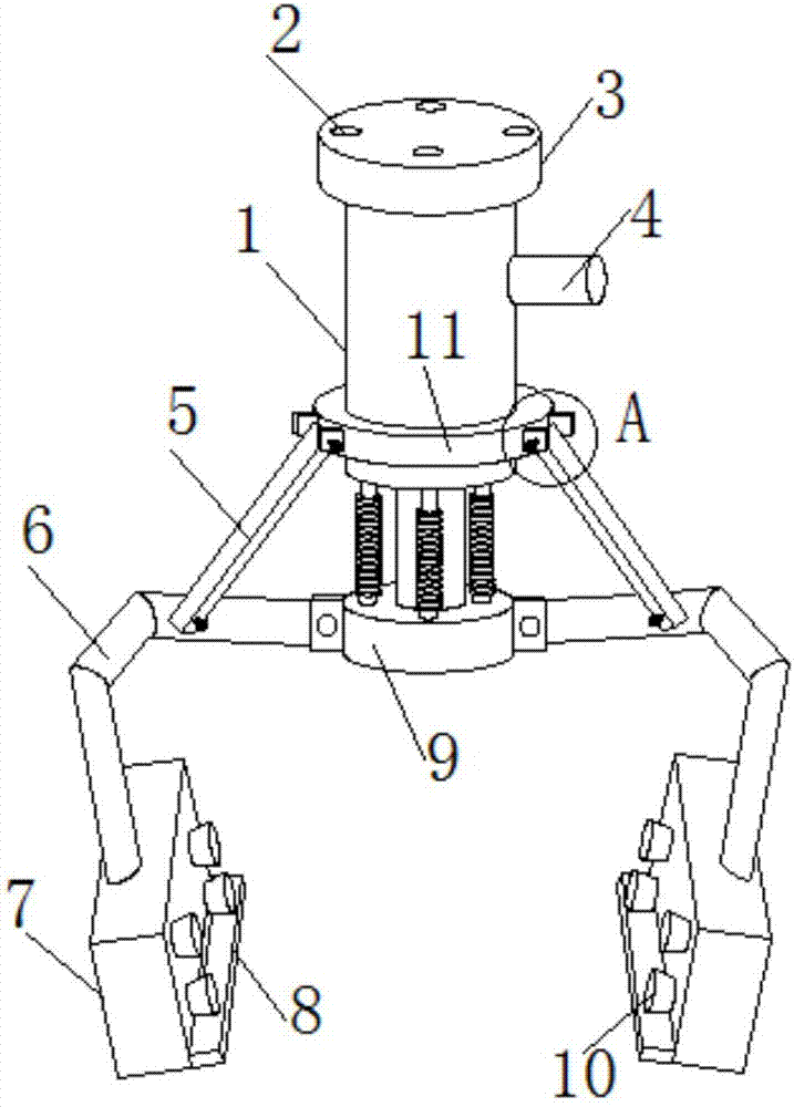
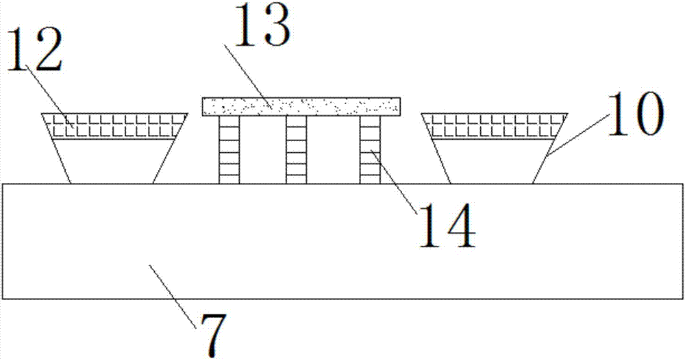
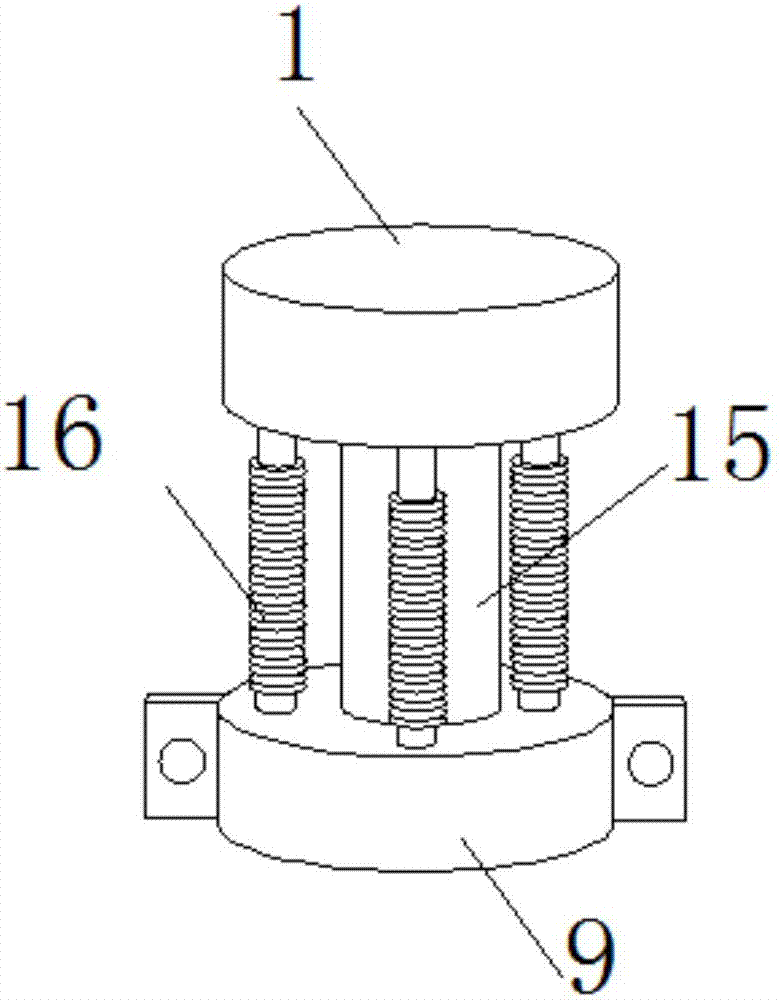
[0025] see Figure 1-5 As shown, a cargo grabbing device for an industrial robot includes a hydraulic column 1, a support rod 5, a mechanical arm 6 and a baffle 7. A connecting pipe 4 is connected to one side of the middle of the hydraulic column 1, and the bottom end of the hydraulic column 1 A collar 11 is welded on the outside, and three sets of support rods 5 are evenly connected to the outside of the collar 11. The collar 11 facilitates the flexible connection between the support rod 5 and the hydraulic column 1 through the protrusion 20 and the fastening bolt 19, and the other end of the support rod 5 is connected through a tight The fixed bolt 19 is movably connected to the mechanical arm 6, which is convenient to drive the mechanical arm 6 to move during work. The bottom of the hydraulic column 1 is movably connected to the telescopic rod 15. The bottom of the telescopic rod 15 is connected to the fixed head 9, and the outside of the fixed head 9 is evenly connected to ...

Embodiment 2

[0027] Additionally, according to Figure 1-5 As shown, the difference between it and the above embodiment is that: the top of the hydraulic column 1 is welded with a mounting head 3, and there are several bolt holes 2 inside the mounting head 3, and the hydraulic column 1 is conveniently connected with the industrial robot through the mounting head 3 and the bolt holes 2. The moving arm is connected, and the grabbing device can move freely during work. Two groups of protruding heads 20 are provided at the connection between the collar 11 and the fixed head 9 and the supporting rod 5 and the mechanical arm 6, and one end of the supporting rod 5 and the mechanical arm 6 is inserted between the two protruding heads 20, and the supporting rod 5 and the mechanical arm 6 are inserted between the two protruding heads 20. The arm 6 is movably connected with the collar 11 and the fixed head 9 respectively through the protruding head 20 and the fastening bolt 19, so that the mechanical...


PUM


Abstract

The invention discloses a cargo grabbing device for an industrial robot. The cargo grabbing device comprises a hydraulic column, bolt holes, a mounting head, a connecting pipe, supporting rods, mechanical arms, baffles, limiting plates, a fixing head, suction discs, a socket ring, electromagnets, extrusion plates, spiral springs, a telescopic rod, shock absorbing springs, chambers, rubber gaskets,fastening bolts and raised heads. The cargo grabbing device has the beneficial effects that the bottom of the hydraulic column is movably connected with the mechanical arms by employing the telescopic rod and the exterior of the hydraulic column is movably connected with the mechanical arms through the supporting rods, so that operation of the mechanical arms is more stable during operation; themechanical arms are comprehensively fixed by the telescopic rod and the supporting rods, so that a cargo is not prone to shake or fall off when the cargo grabbing device grabs the cargo; and the mechanical arms are convenient to contract and can be contracted simply by using the hydraulic column to drive the telescopic rod to move upwards in the hydraulic column. When the telescopic rod moves upwards, the mechanical arms are tightened and grab the cargo, and when the telescopic rod moves downwards, the mechanical arms release the cargo and the cargo falls off. The cargo grabbing device is convenient in use, simple to operate and high in working efficiency.

Description

technical field [0001] The invention relates to a cargo grabbing device, in particular to a cargo grabbing device for industrial robots, belonging to the application field of industrial robots. Background technique [0002] With the continuous development of science and technology, various industrial robots used in industry appear in daily production. Industrial robots have high working efficiency, good safety performance, low cost, and high precision in production and processing. In production, the cargo grabbing device of industrial robots is often used to grab and transport goods. [0003] However, the existing cargo grabbing devices for industrial robots still have certain deficiencies in use. The existing cargo grabbing device used for industrial robots has a simple structure and insufficient stability when grabbing objects, and the cargo often falls, resulting in damage to the cargo. The grabbing device cannot generate strong pressure and friction with the goods, an...

Claims


Application Information

Patent Timeline
Patent Type & Authority Applications(China)
IPC IPC(8): B25J15/02B25J15/06
CPCB25J15/02B25J15/0616
Inventor 黄庚保
Owner GUANGXI RUIKE IND ROBOT CO LTD
Why Eureka
Try Eureka