A device for discharging residual iron from a skimmer

A technology of skimmer and residual iron, which is applied in the field of iron and steel blast furnace pouring, can solve the problems of prolonging working time, cutting deviation, reducing work efficiency, etc., and achieve the effect of improving work efficiency

Inactive Publication Date: 2019-08-09
杜奕飞
View PDF6 Cites 0 Cited by
  • Summary
  • Abstract
  • Description
  • Claims
  • Application Information

AI Technical Summary

Problems solved by technology

[0004] However, because the pneumatic rock drill is heavy and the residual iron eye is a straight hole, not only is the worker holding the pneumatic rock drill, but it is difficult to keep the drill bit of the pneumatic rock drill and the residual iron eye always coincident, and the drilling deviation may occur, and the worker cannot continue for a long time. The operation will prolong the working time, thereby affecting the drilling progress and greatly reducing work efficiency; in addition, when the residual iron eye is drilled through, the residual high-temperature molten iron will flow out of the residual iron eye, which is very likely to burn the workers and cause unnecessary damage. safe question

Method used


Image

  • A device for discharging residual iron from a skimmer
  • A device for discharging residual iron from a skimmer
  • A device for discharging residual iron from a skimmer

Examples


Embodiment Construction

[0032] In order to enable those skilled in the art to better understand the technical solutions in the present invention, the technical solutions in the embodiments of the present invention will be clearly and completely described below in conjunction with the drawings in the embodiments of the present invention. Obviously, the described The embodiments are only some of the embodiments of the present invention, not all of them. Based on the embodiments of the present invention, all other embodiments obtained by persons of ordinary skill in the art without making creative efforts shall fall within the protection scope of the present invention.

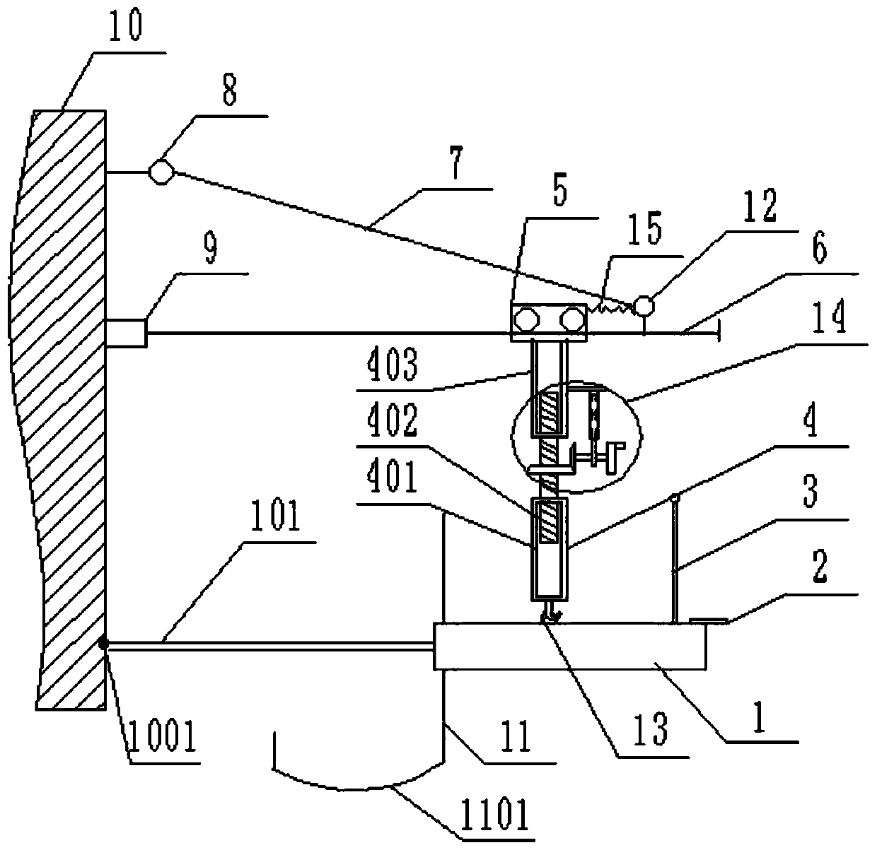
[0033] see figure 1 , figure 1 It is a structural schematic diagram of a device for discharging skimmer iron residues provided in this application. Because the wall thickness of the skimmer is relatively thick, in order to improve the efficiency of drilling through the residual iron eye, a device for discharging the residual iron of t...


PUM

PropertyMeasurementUnit
lengthaaaaaaaaaa

Abstract

The invention discloses a device for discharging residual iron of a slag skimmer. The device comprises a pneumatic rock drill, a supporting cross rod, a supporting oblique rod, a pulley and a riggingturnbuckle, wherein the pulley and the rigging turnbuckle are connected with the supporting cross rod. A first fixed hanging ring and a fixed sleeve are fixed to the outer wall of the slag skimmer, the first fixed hanging ring is located on the upper side of the fixed sleeve, one end of the supporting cross rod is movably inserted into the fixed sleeve, and a second fixed hanging ring is fixedly connected with the other end of the supporting cross rod; and the supporting cross rod and the outer wall of the slag skimmer are perpendicularly arranged, the two ends of the supporting oblique rod are connected to the first fixed hanging ring and the second fixed hanging ring in a hung mode through hooks correspondingly, and a certain included angle is formed between the supporting cross rod andthe supporting oblique rod. According to the device, the efficiency that a residual iron hole is perforated can be improved.

Description

technical field [0001] The present application relates to the technical field of iron and steel blast furnace pouring, in particular to a device for discharging residual iron from a skimmer. Background technique [0002] The blast furnace iron hook is the pouring type iron trench of the blast furnace. After a certain period of use, the blast furnace iron trench needs to be dismantled and re-cast. During the service life of the blast furnace iron trench, there is always residual iron (that is, residual high temperature molten iron), before dismantling, the residual iron in the skimmer needs to be discharged for subsequent dismantling work. [0003] At the bottom of the skimmer, there is a residual iron eye specially for discharging high-temperature molten iron. Since the wall thickness of the skimmer is generally relatively thick, while the wall thickness of the residual iron eye is relatively thin. Iron released. At present, when digging through the residual iron eye, the ...

Claims


Application Information

Patent Timeline
Patent Type & Authority Patents(China)
IPC IPC(8): C21B7/12
CPCC21B7/12Y02P10/20
Inventor 杜奕飞
Owner 杜奕飞
Why Eureka
Try Eureka