
A kind of anti-pull diagonal bracing structure for high pier used for foundation pit support

A pier pull-back type and foundation pit support technology, which is applied in the direction of basic structure engineering, construction, excavation, etc., can solve the problems of high cost, difficulty in earthwork excavation, difficulty in main structure construction, etc., and achieves easy excavation and easy construction of the main structure , the effect of shortening the construction period

Active Publication Date: 2019-08-30
ANHUI URBAN CONSTR DESIGN & RES INST
View PDF2 Cites 0 Cited by
  • Summary
  • Abstract
  • Description
  • Claims
  • Application Information

AI Technical Summary

Problems solved by technology

[0007] The purpose of the present invention is to overcome the deficiencies of the prior art and provide a high pier anti-pull diagonal bracing structure for foundation pit support to solve the difficulty in construction of the main structure, high cost and difficulty in earthwork excavation in the prior art and other technical issues

Method used


Image

  • A kind of anti-pull diagonal bracing structure for high pier used for foundation pit support
  • A kind of anti-pull diagonal bracing structure for high pier used for foundation pit support
  • A kind of anti-pull diagonal bracing structure for high pier used for foundation pit support

Examples


no. 1 example

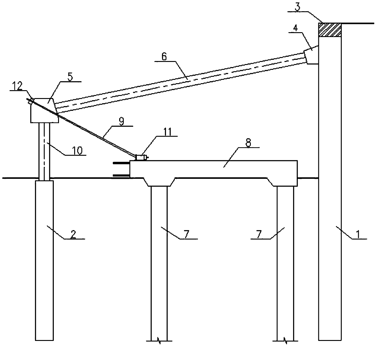
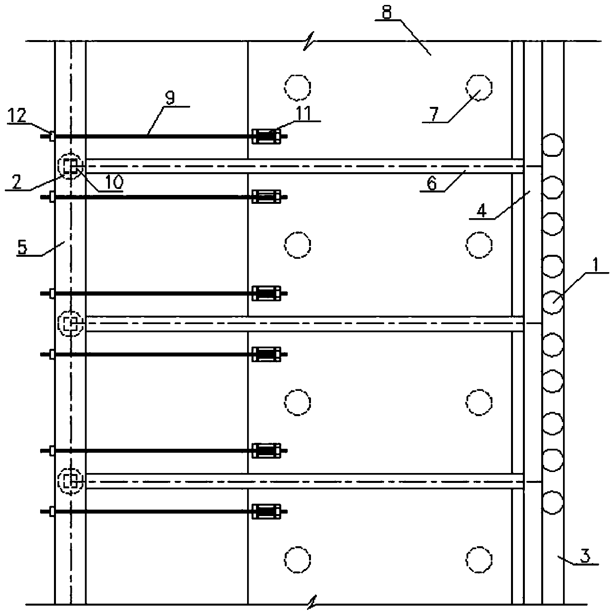
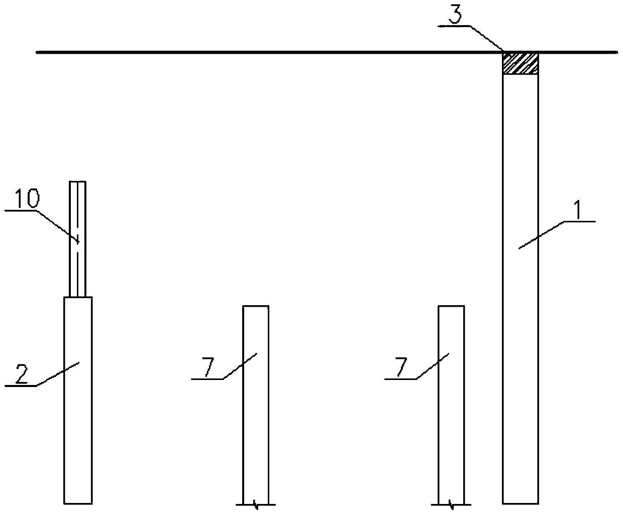
[0032] see image 3 , first set the parameters of enclosure structure 1, buttress pile column 2, and two rows of pile foundation columns 7 according to the specific parameters of the foundation pit, and pre-set the parameters of enclosure structure 1, buttress pile column 2 and two rows of pile foundation columns 7 It is poured into shape, and the enclosure structure 1, the pier column 2, and the two rows of pile foundation columns 7 are arranged parallel to each other; the enclosure structure 1 adopts the method of row piles, and each row of piles is parallel to each other, and the height of the top of the row pile is higher than The height of the top of the foundation pit, so as to be fixedly connected with the crown beam 3; the buttress pile column 2 is formed by a plurality of buttress piles parallel to each other; method; the top of the pier pile and the top of the foundation pile are all arranged at the bottom of the foundation pit; the steel column 10 is constructed on ...

no. 2 example

[0039] The main structure to be built in the foundation pit in this example is the first floor underground, the excavation depth of the foundation pit is 6m, and the plane span is 150m. The surrounding environment is complex, and the deformation control of the foundation pit is strictly required. The internal support adopts the diagonal support in the pit.

[0040] The enclosure structure 1 is specifically composed of a plurality of rows of piles, see figure 2 . The row of piles adopts 900mm diameter bored piles, the piles are 12m long, and form columns at a certain distance. The pile foundation of the main structure adopts 800mm diameter bored piles, and the pile top elevation is 100mm above the bottom of the proposed basement floor structure. The buttress pile column 2 is specifically composed of multiple buttress piles in a row. The buttress piles are 900mm diameter bored piles. The pile top elevation is 200mm below the bottom of the basement floor cushion to be built. T...


PUM


Abstract

The invention discloses a high buttress counter pull type inclined supporting structure used for foundation pit supporting, and relates to the technical field of rock engineering. The structure comprises a building envelope used for supporting the edge of the foundation pit and a buttress pile column which is arranged in the foundation pit and used for supporting the building envelope; a crown beam is arranged on the top of the building envelope, a circuit purlin is arranged on the side wall of the side, close to the foundation pit, of the building envelope, a strip support is arranged on thetop of the buttress pile column, the circuit purlin is connected with the strip support through a supporting arm, two rows of pile foundation columns are arranged between the building envelope and thebuttress pile column and are parallel to the building envelope, the height of the tops of the pile foundation columns is smaller than the height of the top of the strip support, and a sidespan bottomplate is arranged on the tops of the two rows of pile foundation columns for connection; the top of the sidespan bottom plate is connected with the strip support through an inclined pull arm column.The structure can effectively reduce the main construction difficulty, construction efficiency is improved, foundation pit earth and stone digging is facilitated, and the construction cost can be effectively reduced.

Description

technical field [0001] The invention relates to the technical field of geotechnical engineering, in particular to a reverse-pull diagonal bracing structure for a high pier used for foundation pit support. Background technique [0002] At present, the internal supporting structure of foundation pit support used in China is mainly horizontal support and diagonal brace in the pit. For foundation pits with large plane size and shallow depth, diagonal braces in the pit are mostly used, and the materials of the diagonal braces are mostly steel pipes or combined steel. Reliable support reaction force, the diagonal support is set at the bottom of the foundation pit, and the pile foundation is used or the basement floor constructed in the middle is used in advance. The foundation pit earthwork of the existing diagonal brace technology adopts the "pot type" excavation method. The earthwork in the middle is excavated first, and the edge earthwork is excavated to the bottom of the diago...

Claims


Application Information

Patent Timeline
Patent Type & Authority Patents(China)
IPC IPC(8): E02D17/04
Inventor 束冬青蔡敏李彪孟玉孟凡军吴东彪周阳刘少凯刘贵强赵贵生单灿灿张龙飞孙昌兴
Owner ANHUI URBAN CONSTR DESIGN & RES INST
Learn More