
Roller for fixation of dredging cable of pipeline slit remover, and matched fixing method for dredging cable

The technology of a dredging machine and a drum is applied in the field of pipeline dredging and cleaning equipment, which can solve the problems of low equipment efficiency and high energy consumption, and achieve the effects of prolonging the service life, reducing wear and reducing noise.

Active Publication Date: 2018-05-08
郑州中原科技工程研究院有限公司
View PDF8 Cites 0 Cited by
  • Summary
  • Abstract
  • Description
  • Claims
  • Application Information

AI Technical Summary

Problems solved by technology

[0005] The invention proposes a drum for fixing the dredging cable in the pipeline dredging machine, which solves the problems of low efficiency of entering and leaving equipment and large energy consumption during the use of the drum used for fixing the dredging cable in the pipeline dredging machine in the prior art , to further improve the overall efficiency of dredging equipment

Method used


Image

  • Roller for fixation of dredging cable of pipeline slit remover, and matched fixing method for dredging cable
  • Roller for fixation of dredging cable of pipeline slit remover, and matched fixing method for dredging cable
  • Roller for fixation of dredging cable of pipeline slit remover, and matched fixing method for dredging cable

Examples


Embodiment 1

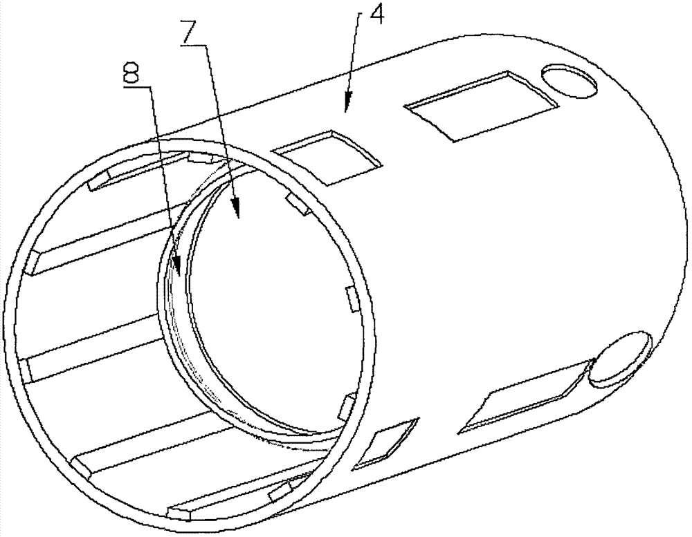
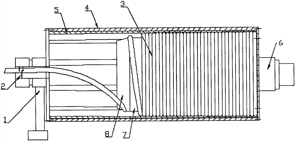
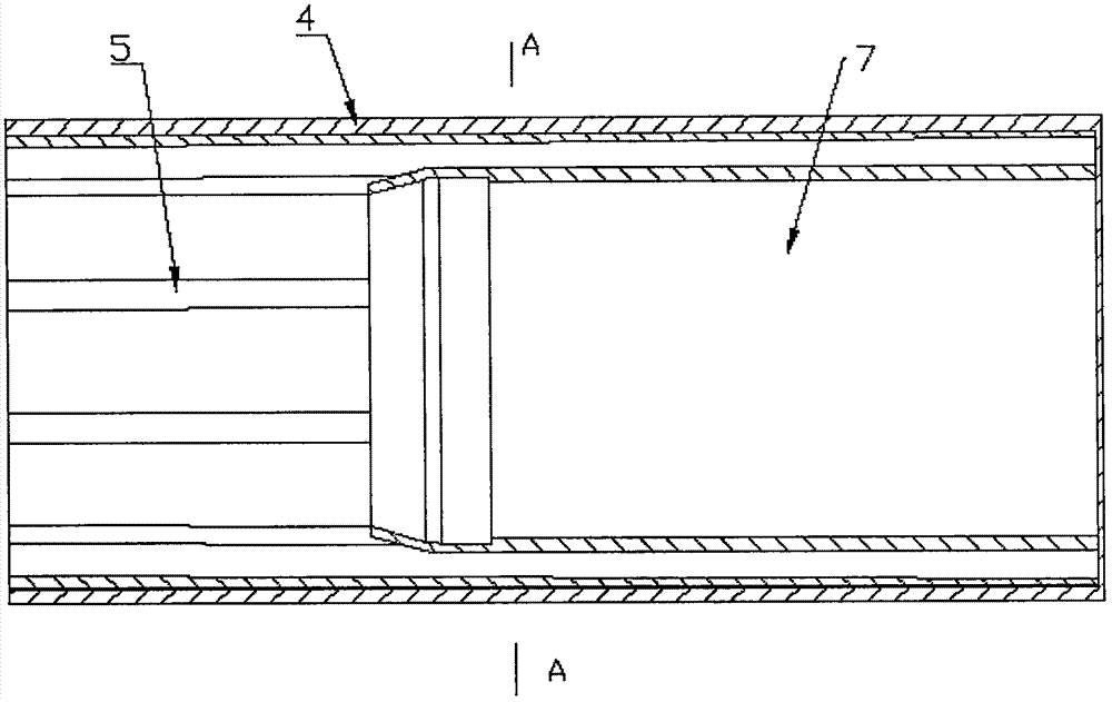
[0028] Such as Figure 1-4 As shown, the present invention provides a drum for fixing the dredging cable in a pipeline dredging machine, comprising an outer layer storage tube 4 and an inner layer sleeve 7 installed coaxially; The blue cover, wherein, the outer surface of the right end flange cover is successively installed with the right end concentric shaft and the drum power source that drives the right end concentric shaft to rotate, and the middle part of the left end flange cover is provided with a hollow shaft communicating with the inner cavity of the drum, and a circlip 1 is fitted on the hollow shaft via a bearing, and the spring device 1, which limits the degree of freedom of the flexible shaft on the vertical plane, is connected to the clamping power source; the flexible shaft storage cavity is formed between the outer storage tube 4 and the inner sleeve 7, so that The flexible shaft can be wound in the outer storage tube 4 circle by circle in the cavity until it p...

Embodiment 2

[0039] The principle of this embodiment is the same as that of Embodiment 1, the specific difference is that the guide tube 8 is clamped on the inner sleeve 7 . Make the transition surface smoother, and further improve the guiding effect on the soft axis. In this embodiment, the hydraulic motor of the circlip device 1 is replaced by a conventional belt drive.

[0040] In addition, if Figure 5 As shown, the width of the limiting plate corresponds to a central angle of 36 degrees. In actual working conditions, the width of the limiting plate roughly corresponds to the width of the gap. On the one hand, it ensures the realization of the limit, and on the other hand, it saves materials. Reduce friction.


PUM


Abstract

The invention discloses a roller for fixation of a dredging cable of a pipeline slit remover, and a matched fixing method for the dredging cable and aims to provide a roller for fixation and enablinga soft shaft to quickly and stably come in and out, and a matched soft shaft fixing method. The roller comprises an external storage roller and an internal sleeve roller coaxial to the external storage roller, wherein two ends of the external storage roller are equipped with flanges; an external layer supporting plate is connected with a roller power source; the other empty end of the external storage cylinder is provided with a jump ring device; the jump ring device is connected with a clamping power source; a soft shaft storage empty cavity is formed by the external storage roller and the internal sleeve roller, so the soft shaft can wind in the cavity loops by loops; the sleeve roller and an outlet end of the soft shaft are both connected with an independent power source, differentiallyrotating in the same or opposite direction; freedom degree of the soft shaft is limited; and the soft shaft can come in and out with high efficiency under effective guidance.

Description

technical field [0001] The invention relates to the field of pipeline dredging and decontamination equipment, in particular to a roller for fixing a desilting cable in a pipeline desilting machine and a matching method for fixing the desilting cable. Background technique [0002] With the rapid development of social economy, more and more people are entering a well-off life, coupled with the steady advancement of urbanization, more and more rural areas have become cities and towns, and the urban population has increased sharply, followed by domestic sewage. A large increase, many times because the sewer pipes are blocked or the water is not smooth, the sewage overflows, affects the city appearance, and has a serious impact on people's life and work. The corresponding pipeline dredging technology is mostly used in municipal maintenance equipment. Its main working principle is to use the rotating cables arched into the pipeline to achieve agitation of the inner space of the pi...

Claims


Application Information

Patent Timeline
Patent Type & Authority Applications(China)
IPC IPC(8): E03F9/00E03F7/00B65H75/44
CPCE03F7/00E03F9/005B65H75/44B65H75/4402Y02W30/82
Inventor 吴博吴彦云扶涛涛陈振广吴硕闫磊
Owner 郑州中原科技工程研究院有限公司
Learn More