Serpentine tube microchannel heat exchanger
A technology of microchannel heat exchangers and serpentine tubes, applied in lighting and heating equipment, evaporators/condensers, refrigerators, etc. Problems such as large process flow, to achieve the effect of improving heat exchange efficiency, various layout methods, and increasing temperature difference
- Summary
- Abstract
- Description
- Claims
- Application Information
AI Technical Summary
Problems solved by technology
Method used
Image
Examples
Embodiment 1
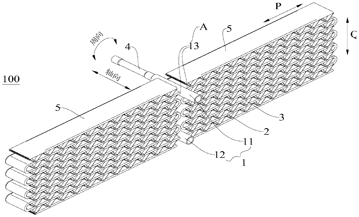
[0056] figure 1 The structure of the serpentine tube microchannel heat exchanger 100 in the first embodiment is shown.
[0057] In Embodiment 1, the serpentine tube microchannel heat exchanger 100 includes an inlet header 11 and an outlet header 12 parallel to each other, and the two headers 1 are respectively formed as circular tubes.
[0058] Each header 1 is provided with a set of first hole groups A, the first hole group A includes two flow holes 13, and the central axes of the two flow holes 13 in each first hole group A are in the corresponding The projections on the central axis of the header 1 coincide. The long side of each flow hole 13 is substantially parallel to the axial direction of the corresponding header 1 .
[0059] The central axes of the two flow holes 13 are symmetrical to the central axis of the corresponding header 1 , or in other words, the included angle between the central axes of the two flow holes 13 on the cross section of the header 1 is 180 deg...
Embodiment 2
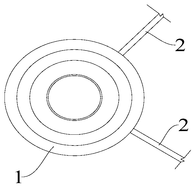
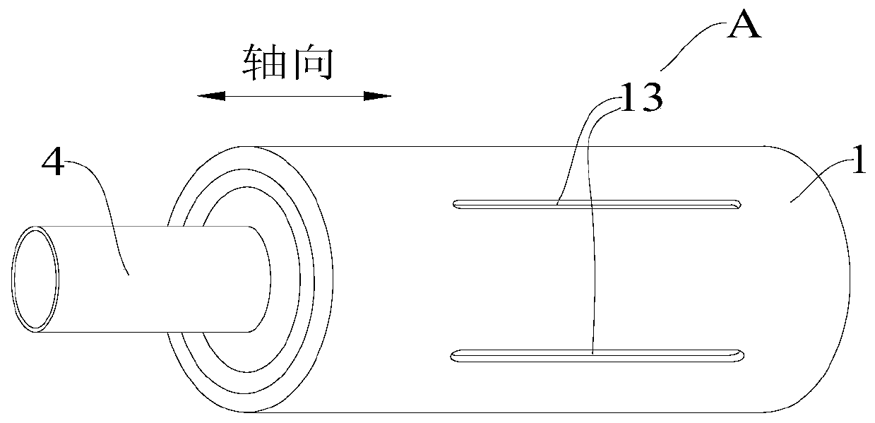
[0062] figure 2 and image 3 The structure of the header 1 of the serpentine tube microchannel heat exchanger 100 in the second embodiment is shown.
[0063] In the second embodiment, the collecting pipe 1 is formed as a round pipe, and the collecting pipe 1 is provided with a first hole group A, and the first hole group A includes two flow holes 13, and two of the first hole group A The projections of the central axes of the flow holes 13 on the central axes of the corresponding headers 1 coincide, and the long sides of each flow hole 13 are substantially parallel to the axial direction of the corresponding headers 1 . Therefore, the cross-section of the header 1 is not limited by the width of the flat tube 2, and the diameter of the header 1 can be as small as possible under the conditions of pressure bearing capacity and welding, so as to save the material cost of the header 1.
[0064] In the second embodiment, the included angle between the projections of the central a...
Embodiment 3
[0067] Figure 4 The structure of the header 1 in the third embodiment is shown, the structure of the header 1 is substantially the same as that of the header 1 of the second embodiment, the difference is that in the third embodiment, each header 1 A reinforcing rib 14 is connected between the two flow holes 13, and the shape of the reinforcing rib 14 can also be called a reinforcing rib to enhance the pressure bearing capacity.
[0068] The third embodiment is proposed for illustration. In the embodiments of the present invention (including the other eight embodiments), a reinforcing rib 14 is connected between at least two flow holes 13 on each header 1 .
PUM
 Abstract
Description
Claims
Application Information
 - R&D
- Intellectual Property
- Life Sciences
- Materials
- Tech Scout
- Unparalleled Data Quality
- Higher Quality Content
- 60% Fewer Hallucinations
Browse by: Latest US Patents, China's latest patents, Technical Efficacy Thesaurus, Application Domain, Technology Topic, Popular Technical Reports.
© 2025 PatSnap. All rights reserved.Legal|Privacy policy|Modern Slavery Act Transparency Statement|Sitemap|About US| Contact US: help@patsnap.com


