Magic cube, surface rotation sensor and axis structure thereof

A technology of rotating sensor and Rubik's cube, applied in the field of Rubik's Cube, which can solve the problems of single function of Rubik's Cube, inability to communicate with external electronic devices, and inability to fit the sensor volume and area.

Pending Publication Date: 2020-11-17
汕头市澄海区科梦智能科技有限公司
View PDF1 Cites 0 Cited by
  • Summary
  • Abstract
  • Description
  • Claims
  • Application Information

AI Technical Summary

Problems solved by technology

[0003] At present, the commonly used Rubik's Cube has a single function, cannot communicate with external electronic devices, and lacks interest
In order to improve the fun of Rubik's Cube operation, some electronic Rubik's Cubes have appeared in the prior art, that is, electronic components such as sensors are arranged on the Rubik's Cube to detect the surface rotation information of the Rubik's Cube, etc., but in the prior art due to problems such as sensor volume and area It cannot be put into the inner ball in the center of the Rubik's Cube, which makes the internal structure of the Rubik's Cube more complicated
For example, the Chinese invention patent application with the publication number CN106110651A discloses a smart Rubik's Cube and its use of the induction axis structure timing method, wherein the state signal sending group for generating the state signal, that is, the sensor is arranged on the tubular shaft outside the Rubik's cube inside the inner sphere The central block, the data and electrical connection between the sensor and the i

Method used


Image

  • Magic cube, surface rotation sensor and axis structure thereof
  • Magic cube, surface rotation sensor and axis structure thereof
  • Magic cube, surface rotation sensor and axis structure thereof

Examples


Embodiment 1

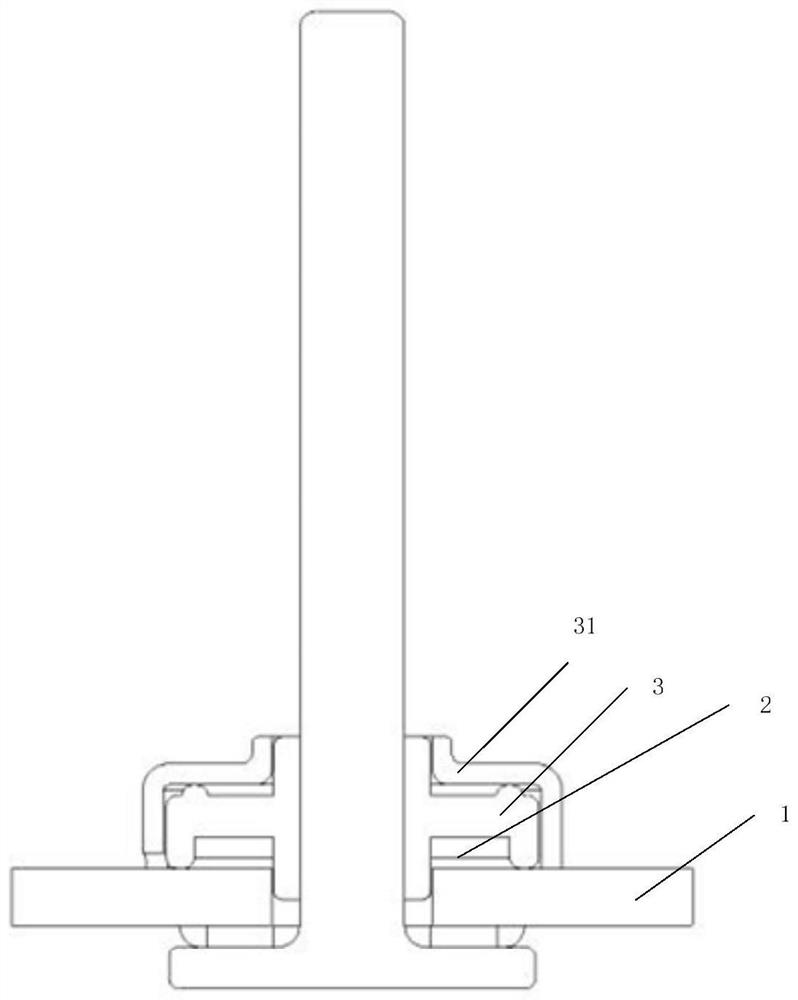
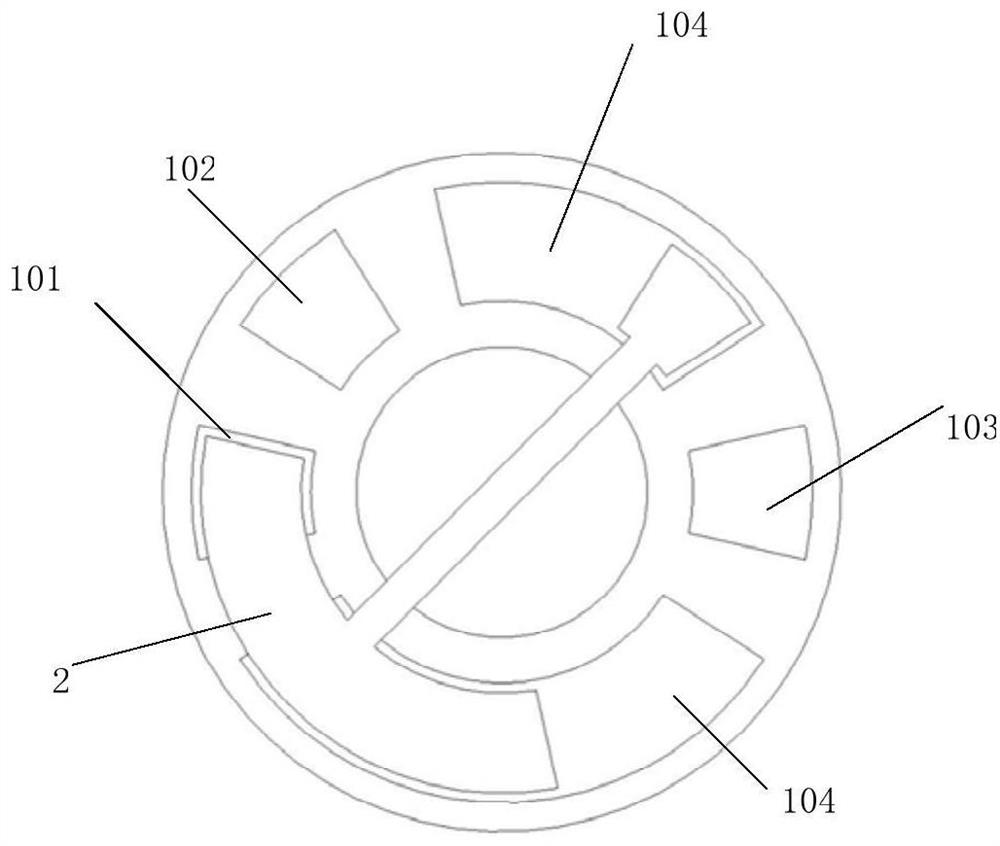
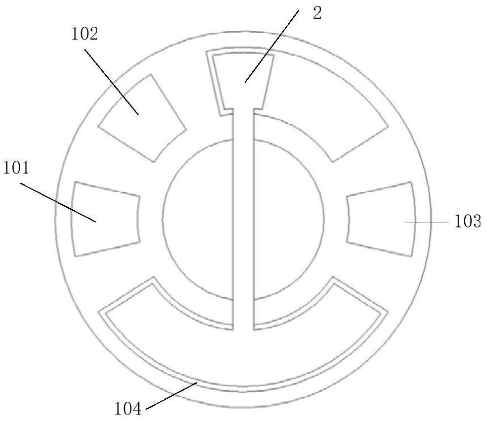
[0061] This embodiment discloses a surface rotation sensor of Rubik's Cube, such as figure 1 As shown, including a code wheel 1, a first brush 2 and a first rotor 3, the code wheel is provided with a first electrode and a second electrode, and the first electrode and the second electrode are arranged on the same first circumference of the code wheel surface; The first brush is installed on the first rotor and arranged along the first circumference where the first electrode and the second electrode are located. The first brush is driven by the first rotor to face the first electrode and the second electrode along the first circumference. Rotate; when the first brush rotates to the relative position of the first electrode, it contacts with the first electrode.

[0062] The first electrode includes a plurality of electrodes, and the number n of electrodes in the first electrode is set according to the angle detection accuracy of the surface rotation sensor for the magic aspect. ...

Embodiment 2

[0084] This embodiment discloses a surface rotation sensor of Rubik's Cube, which differs from the surface rotation sensor of Rubik's Cube in Embodiment 1 only in that Figure 5 As shown, the surface rotation sensor of the Rubik's Cube in this embodiment also includes a second rotor 4 and a second brush 5, and a third electrode and a fourth electrode are also provided on the code disc.

[0085] In this embodiment, the third electrode and the fourth electrode are arranged on the same circumference of the code disc surface, and this circumference is defined as the second circumference; The second brush is installed on the second rotor, and is driven by the second rotor to rotate relative to the third electrode and the fourth electrode along the second circumference; when the second brush rotates to the position opposite to the third electrode, the third electrode contacts.

[0086] In this embodiment, the third electrode includes a plurality of electrodes, and the number n of t...

Embodiment 3

[0099] This embodiment discloses a surface rotation sensor of Rubik's Cube, such as Figure 9 As shown, the only difference with the surface rotation sensor of Rubik's Cube in Embodiment 1 is that the surface rotation sensor of Rubik's Cube in this embodiment also includes a second rotor 4, a second brush 5, a third rotor 6 and a third brush 7, The code wheel is also provided with a third electrode, a fourth electrode, a fifth electrode and a sixth electrode.

[0100] In this embodiment, the third electrode and the fourth electrode are arranged on the same circumference of the code disc surface, and this circumference is defined as the second circumference; The brush is installed on the second rotor, and it is driven by the second rotor to rotate relative to the third electrode and the fourth electrode along the second circumference; when the second brush rotates to the position opposite to the third electrode, the third electrode Contact; the third electrode includes a plurali...


PUM


Abstract

The invention discloses a magic cube and a surface rotation sensor and an axis structure thereof, the surface rotation sensor of the magic cube comprises a coded disc, a first electric brush and a first rotor, the coded disc is provided with a first electrode and a second electrode, and the first electrode and the second electrode are arranged on the first circumference of the coded disc surface;the first electric brush is installed on the first rotor and arranged along a first circumference where the first electrode and the second electrode are located, and the first electric brush is drivenby the first rotor to rotate relative to the first electrode and the second electrode along the first circumference; wherein the first electrode comprises a plurality of electrodes, and n electrodesin the first electrode are respectively and correspondingly arranged on any n equal parts of the equal part first circumference; arranging a first electric brush along any equal first circumference inthe equal first circumferences; and the second electrode is arranged on the first circumference, so that the first electric brush is contacted with the second electrode when rotating to any position.The surface rotation sensor of the magic cube has the advantages of being simpler in structure and smaller in size.

Description

technical field [0001] The present invention relates to the technical field of Rubik's Cube, in particular to Rubik's Cube and its face rotation sensor and axis structure. The Rubik's Cube in the present invention covers Rubik's Cube intellectual toys, specifically referring to all Rubik's Cube intellectual toys that have entered the WCA (International Rubik's Cube Association) competition. Rubik's cube of order 2~7, pyramid Rubik's cube, 12-hedron 5 magic ball, oblique Rubik's cube and SQ Rubik's cube. Background technique [0002] Rubik's Cube, also known as Rubik's Cube, is called Rubik's Cube in Taiwan, China, and is called Rubik's Cube in Hong Kong, China. The English name is: Rubik's Cube. Toys are loved by everyone. Rubik's cube restoration refers to the process of Rubik's cube from non-original state to original state. It is a process integrating observation, hands-on and imagination. It can cultivate people's hands-on, brain-moving ability, training memory, spati...

Claims


Application Information

Patent Timeline
IPC IPC(8): A63F9/08
CPCA63F9/0826
Inventor 陈永煌刘寄张乐
Owner 汕头市澄海区科梦智能科技有限公司
Why Eureka
Try Eureka