
Roof frame structure with single-layer and double-layer roof combination of two-stage stepper

A technology of secondary step and skeleton structure, applied in the superstructure, superstructure sub-assemblies, vehicle parts, etc., can solve the problems of mold development cost and long cycle, height difference of decorative air ducts, standing height space limitation, etc. Achieve the effect of perfecting product chain structure, reducing development cost and cycle, and reducing weight

Active Publication Date: 2018-03-09
ANHUI ANKAI AUTOMOBILE
View PDF8 Cites 0 Cited by
  • Summary
  • Abstract
  • Description
  • Claims
  • Application Information

AI Technical Summary

Problems solved by technology

[0002] At present, for gas-fired bus models with gas cylinders on top, it is necessary to use the space of the double roof to sink the gas cylinders. For the second-level scooters, in order to ensure the standing space behind the middle door, it is necessary to: Later, it is designed into a single-layer roof structure. This design scheme requires the development of single-layer roof transition moldings. The mold development cost and cycle are longer, and there is a height drop after the decoration air duct is installed, and the mold development cost and cycle are longer; (2) The back of the middle door is designed as a double-layer roof structure. The standing height space of this design scheme is limited, and the frame is heavy

Method used


Image

  • Roof frame structure with single-layer and double-layer roof combination of two-stage stepper
  • Roof frame structure with single-layer and double-layer roof combination of two-stage stepper
  • Roof frame structure with single-layer and double-layer roof combination of two-stage stepper

Examples


Embodiment Construction

[0023] The present invention will be further described below in conjunction with accompanying drawing:

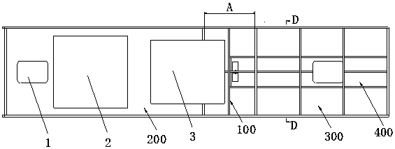
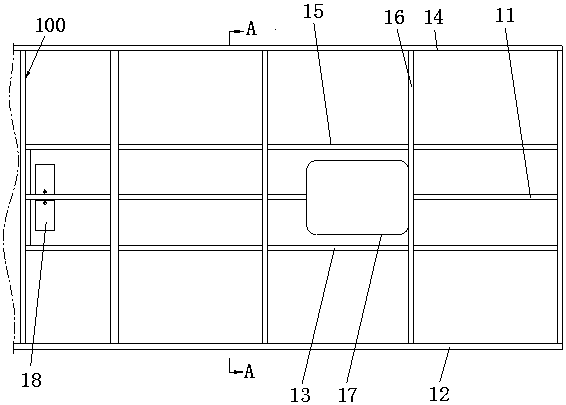
[0024] like figure 1 , figure 2 The roof frame structure of a single-layer roof combined with a two-stage stepper shown includes a first roof frame area 200 located in front of the center position 100 of the middle door and a second roof frame area 300 located behind the center position 100 of the center door. The first roof frame area 200 is a double-layer roof structure, the second roof frame area 300 is a single-layer roof structure in the middle aisle area 400, and the two sides of the middle aisle area 400 are double-layer roof structures. The air duct is in the same plane as the air duct 500 of the second roof frame region 300 . figure 1 The position of part A marked in is the position of the middle door, and the center position 100 of the middle door is the dividing line between the first roof frame area 200 and the second roof frame area 300, and the first roof f...


PUM


Abstract

The invention relates to a second-level stepping vehicle top framework structure combining the single-layer top with the double-layer top. The structure comprises a first top framework area located in front of the center of a middle door and a second top framework area located behind the center of the middle door; the first top framework area is of a double-layer top structure, the portion, in a middle corridor area, of the second top framework area is of a single-layer top structure, the portions, on the two sides of the middle corridor area, of the second top framework area are of a double-layer top structure, and an air channel of the first top framework area and an air channel of the second top framework area are located in the same plane. According to the technical scheme, the center of the middle door serves as a boundary line, the first top framework area in front of the center of the middle door is designed to be of the double-layer top structure, the second top framework area behind the center of the middle door is designed to be of the structure combining the single-layer top with the double-layer top, the standing height space in a vehicle behind the middle door and the installing consistency of the air channels in the vehicle are guaranteed, the developing cost of interior molds is reduced, the developing cycle of the interior molds is shortened, and meanwhile the finished vehicle weight is reduced.

Description

technical field [0001] The invention relates to the field of passenger cars, in particular to a roof frame structure with a single-layer and double-layer roof combination for a two-stage stepper. Background technique [0002] At present, for gas-fired bus models with gas cylinders on top, it is necessary to use the space of the double roof to sink the gas cylinders. For the second-level scooters, in order to ensure the standing space behind the middle door, it is necessary to: Afterwards, it is designed into a single-layer roof structure. This design scheme requires the development of single-layer roof transition moldings. The mold development cost and cycle are longer, and there is a height drop after the decoration air duct is installed, and the mold development cost and cycle are longer; (2) The back of the middle door is designed as a double-layer roof structure. The standing height space of this design scheme is limited, and the frame is heavy. Contents of the inventi...

Claims


Application Information

Patent Timeline
Patent Type & Authority Patents(China)
IPC IPC(8): B62D25/06
CPCB62D25/06
Inventor 甘大利赵理想王泽平张立辉张云凤
Owner ANHUI ANKAI AUTOMOBILE
Learn More