Automatic driving environmental perception system based on vehicle-road coordination

An automatic driving and environment perception technology, applied in the field of automatic driving environment perception system, can solve the problems of large impact on sensor performance of perception range, difficult to fuse sensor data, easy to disassemble, etc.

Inactive Publication Date: 2018-05-08
浙江海康智联科技有限公司
View PDF9 Cites 185 Cited by
  • Summary
  • Abstract
  • Description
  • Claims
  • Application Information

AI Technical Summary

Problems solved by technology

[0004] (1) The vehicle perception range is greatly affected by the performance of the sensor. The current maximum perception distance is about 200 meters, and the perception range for high-speed vehicles is even smaller;
[0005] (2) The perception range is easily affected by obstacles, and it is difficult to achieve a comprehensive perception of the surrounding environment. The current autonomous vehicle perception technology cannot realize the situation ahead by crossing obstacles, and cannot solve the problem of driving safety under the condition of visual obstruction;
[0006] (3) The independent environment perception system of each self-driving vehicle brings challenges to the autonomous driving formation driving. It is difficult to integrate the sensor data of all vehicles in the fleet when the autonomous driving vehicles are driving in formation, resulting in poor robustness of the fleet system and easy disintegration;
[0007] (4) The current high-precision maps have problems such as low update frequency and high acquisition and production costs, which are difficult to meet the actual needs of autonomous vehicles

Method used


Image

  • Automatic driving environmental perception system based on vehicle-road coordination
  • Automatic driving environmental perception system based on vehicle-road coordination

Examples


Embodiment Construction

[0039] The technical solution of the present invention will be described in further detail below in conjunction with the accompanying drawings and embodiments, and the following embodiments do not constitute a limitation of the present invention.

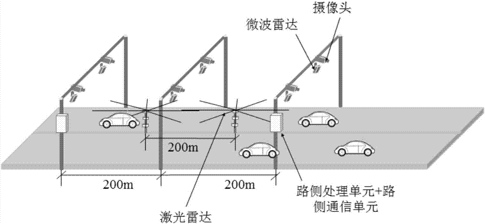
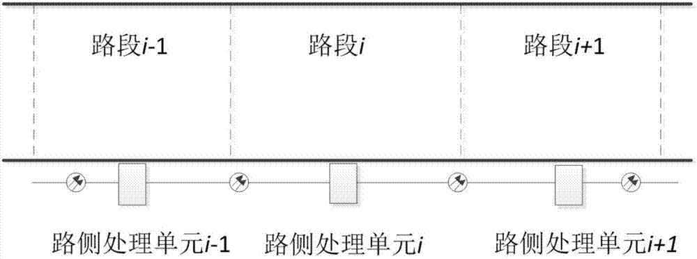
[0040] The rapid development of communication technology has made low-latency communication between vehicles and between vehicles and infrastructure a reality. Traditional DSRC and short-range communication technologies such as LTE-V2X, which are rapidly developing at this stage, have been able to achieve communication with a delay of less than 100 milliseconds between vehicles and between vehicles and infrastructure. In the future 5G era, the delay will reach 1 millisecond. The development of short-distance, low-latency communication technology provides a new way of thinking for the realization of autonomous driving. This technical solution is based on the construction of an environmental perception system on the roadside, and trans...


PUM


Abstract

The invention discloses an automatic driving environmental perception system based on vehicle-road coordination. The system includes a roadside sensor, a roadside processing unit and a roadside communication unit which are arranged on a road segment divided according to a set distance. The roadside sensor includes a camera, a laser radar, and a microwave radar, and is used for acquiring road information of a road. The roadside processing unit is used for receiving the road information acquired by the roadside sensor, recognizing and processing the road information, then converting the road information into a united world coordinate system, fusing and marking the converted data in a high-precision map, splicing the high-precision maps of adjacent road sections to form semantic road environment information, and transmitting the semantic road environment information to the roadside communication unit. The roadside communication unit is used for sending out the semantic road environment information by using wireless communication technology. The automatic driving environmental perception system, by using the roadside sensor, updates the high-precision map in real time according to theacquired road dynamic characteristic data on the basis of the original high-precision map, so as to provide a global environmental perception capability for the safe driving of an autonomous vehicle.

Description

technical field [0001] The invention belongs to the technical field of intelligent networked transportation, and in particular relates to an automatic driving environment perception system based on vehicle-road coordination. Background technique [0002] As the most cutting-edge technology in the field of intelligent transportation, autonomous driving technology includes vehicle environment perception, path planning and decision-making, and vehicle motion control. At this stage, with the development of artificial intelligence and deep learning processing chips, the three autonomous driving technologies have all developed rapidly. However, in order to realize the vehicle’s comprehensive perception of the surrounding environment, each self-driving vehicle needs to be equipped with complex, expensive, and various sensor equipment, resulting in high vehicle costs. According to the evolution of the autonomous route, the commercialization of self-driving cars The process is slow....

Claims


Application Information

Patent Timeline
IPC IPC(8): G08G1/0967
CPCG08G1/096725G08G1/096783G08G1/0116
Inventor 温熙华程元晖李志伟刘彦斌刘云鹏方志远
Owner 浙江海康智联科技有限公司
Why Eureka
Try Eureka