
Driving-vehicle-based blind zone detection method and apparatus, terminal, and vehicle

A detection method and vehicle technology, applied in traffic control systems, signal devices, instruments, etc. of road vehicles, can solve problems such as limited detection distance, difficult distinction of drivers, unsuitable for vehicle detection and early warning, etc. Response time, easy-to-see results

Inactive Publication Date: 2018-05-08
BEIJING CHJ AUTOMOTIVE TECH CO LTD
View PDF7 Cites 22 Cited by
  • Summary
  • Abstract
  • Description
  • Claims
  • Application Information

AI Technical Summary

Problems solved by technology

However, both the radar and the camera have the problem of limited detection distance, which is only suitable for early warning during low-speed driving, not suitable for detection and early warning of high-speed vehicles
[0004] Moreover, when the existing detection and early warning equipment performs early warning prompts, if there are multiple detection devices in different areas in the vehicle, it is often difficult for the driver to distinguish which area is dangerous. At this time, the driver still needs to pass through the vehicle. The display of the central control system that displays the status of each detection device to confirm
In this way, the driver needs to shift his sight, so that the problem of vehicle blind spot detection cannot be fundamentally solved

Method used


Image

  • Driving-vehicle-based blind zone detection method and apparatus, terminal, and vehicle
  • Driving-vehicle-based blind zone detection method and apparatus, terminal, and vehicle
  • Driving-vehicle-based blind zone detection method and apparatus, terminal, and vehicle

Examples


Embodiment Construction

[0055]Exemplary embodiments of the present invention will be described in more detail below with reference to the accompanying drawings. Although exemplary embodiments of the present invention are shown in the drawings, it should be understood that the invention may be embodied in various forms and should not be limited to the embodiments set forth herein. Rather, these embodiments are provided for more thorough understanding of the present invention and to fully convey the scope of the present invention to those skilled in the art.

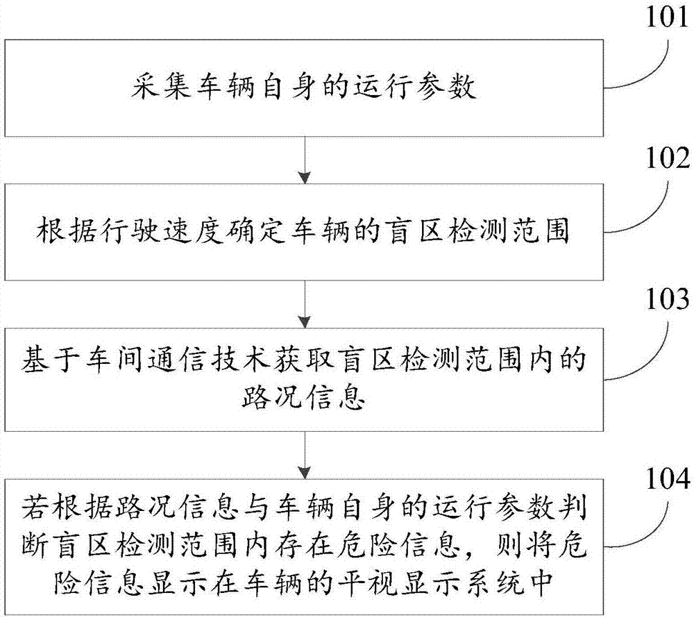
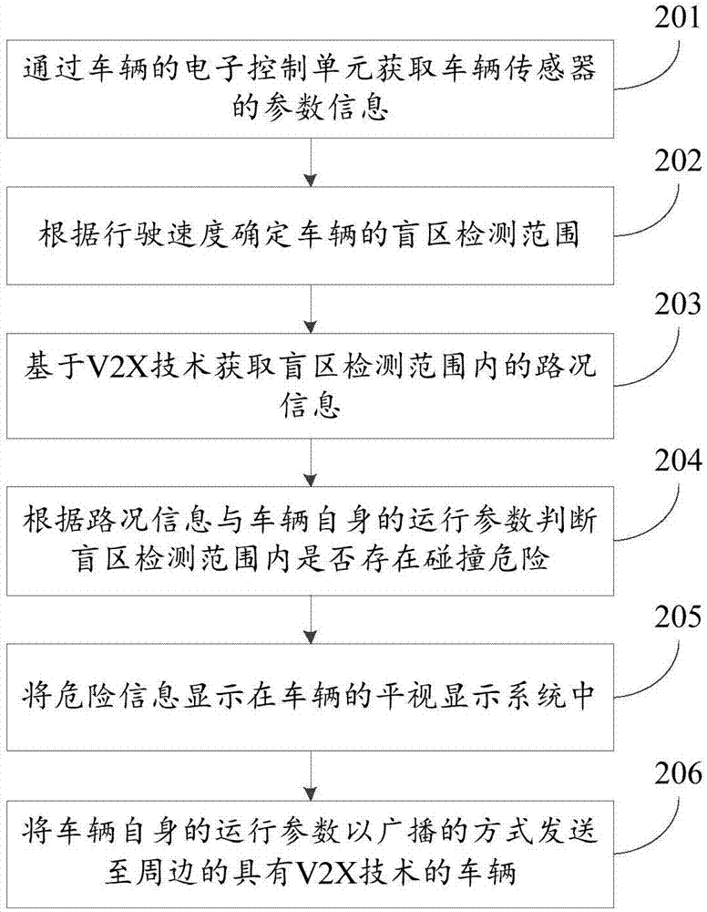
[0056] For the driving vehicle, the embodiment of the present invention provides a blind spot detection method based on the driving vehicle, which uses the vehicle-to-vehicle communication technology (V2X, Vehicle To Everything) to obtain the road condition information within a certain range around the vehicle, and detects potential dangers through the head-up view. The display system (HUD, Head Up Display) is displayed directly in front of the d...


PUM


Abstract

The invention, which relates to the field of the smart car technology, discloses a driving-vehicle-based blind zone detection method and apparatus, a terminal, and a vehicle so that the potential riskaround the vehicle during a driving process can be displayed by using a head-up display system so as to warn the driver for safety driving. The method comprises: running parameters of a vehicle itself are collected, wherein the running parameters include a current running speed of the vehicle; according to the running speed, a blind zone detection range of the vehicle is determined; on the basisof a vehicle-to-vehicle communication technology, road condition information in the blind zone detection range is obtained; and if dangerous information exists in the blind zone detection region basedon the road condition information and the running parameters of the vehicle, the dangerous information is displayed in the head-up display system of the vehicle. The driving-vehicle-based blind zonedetection method and apparatus, the terminal, and the vehicle are mainly used for detection and early warning for the blind zone of the vehicle.

Description

technical field [0001] The invention relates to the technical field of smart cars, in particular to a blind spot detection method, device, terminal and vehicle based on a driving vehicle. Background technique [0002] During the driving process of the car, if the driver needs to know whether there are vehicles or dangers around, especially in the blind spot of the vehicle, the most primitive and direct way is to observe through the driver's naked eyes. However, when observing the blind spot of the vehicle, the driver's line of sight must not be able to take into account the direction of travel of the vehicle, so that when unexpected situations occur, traffic accidents are easy to occur. [0003] Based on this problem, the blind spot detection devices currently configured for vehicles mainly include driving radar and cameras. Among them, driving radars commonly include front radar, rear radar and side orientation radar, which are used to detect objects around the vehicle; si...

Claims


Application Information

Patent Timeline
IPC IPC(8): G08G1/16B60Q9/00
CPCB60Q9/008G08G1/161G08G1/166
Inventor 马东辉勾晓菲
Owner BEIJING CHJ AUTOMOTIVE TECH CO LTD
Learn More